In this section you will understand how you can add a controller to our KloudManage software, a step-by-step guide to how you can setup the cameras, configure them, and later view the captured data from the video gallery and play it back. This helps you analyse customer behaviour in physical spaces like, malls, retail stores, and event venues, among others. You can also find out how to integrate Vision with Insights so you can understand footfall patterns, monitor social distancing, or detect specific objects.
This guide is designed to give you step-by-step instructions, valuable tips, and best practices to so you navigate and harness KloudVision effectively, thus equipping you to utilise KloudVision to the best of its abilities.
Once Installation is complete, we can proceed to the next step, which involves adding the KloudController to Kloud Manage Application.
For that login to the Kloud Manage Application.
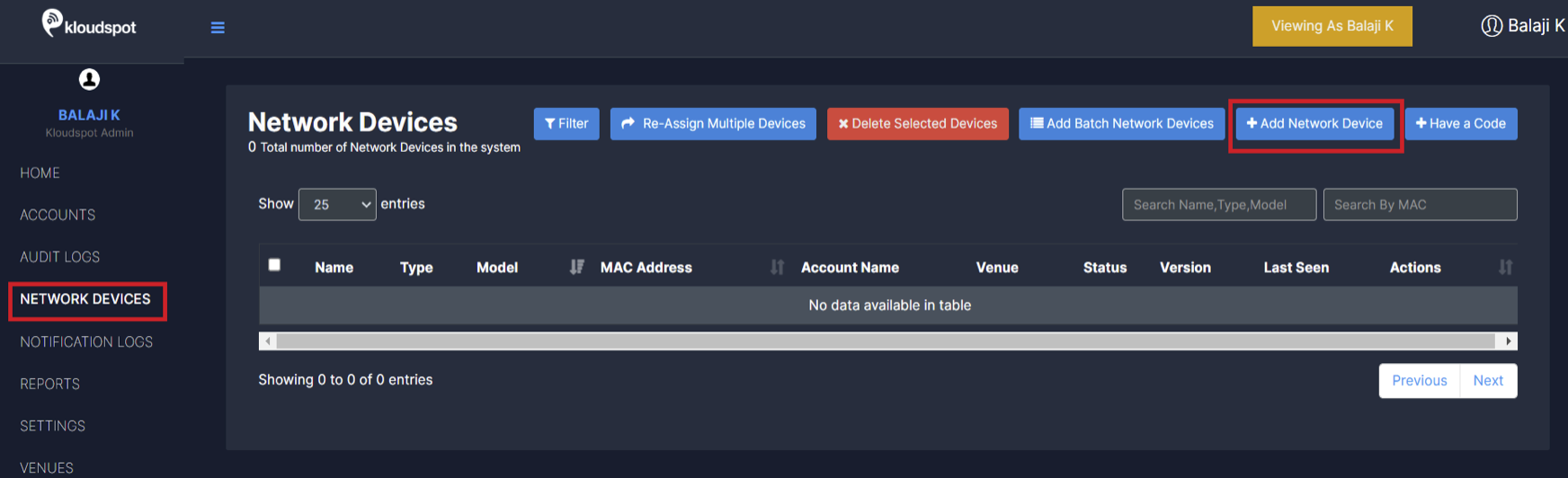
Navigate to NETWORK DEVICES > Add Network Devices.
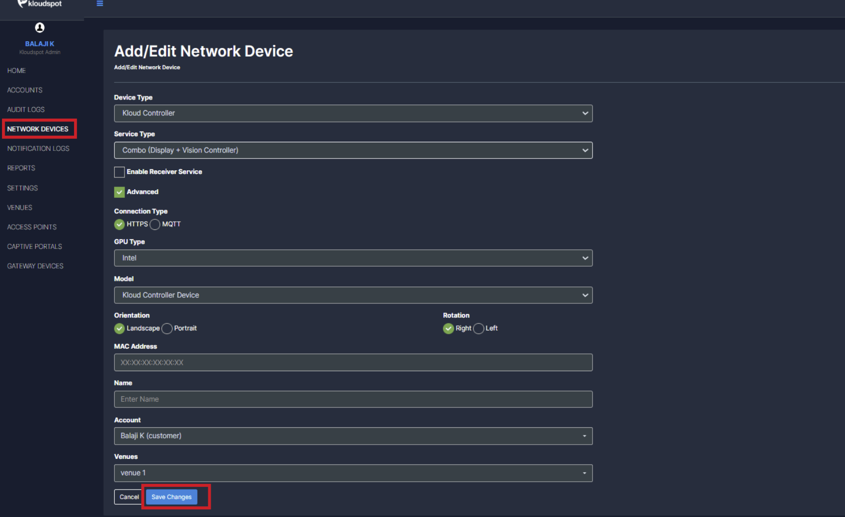
• Enter the following in the window that opens and click the Save Changes button.
Device Type: Select Kloud Controller from the dropdown list.
Service Type:
Select Vision if only Vision Service is required
Select Display if only Display Service is required
Combo device (Display + Vision controller) from the dropdown list if both Display and Vision is required
NOTE: If you’re unsure about the specific service, select “Combo device.” If you add the device as “Vision” and later need to enable “Display,” you will have to delete and re-add the device, which may result in data loss.
• Connection Type: Select your connection type
HTTPS – Use HTTPS for a secure, encrypted connection over port 443.
MQTT – Choose MQTT for low-latency real-time communication
• GPU Type: Select your GPU Type
KloudController supports both Intel and NVIDIA GPUs. we can select the appropriate GPU type based on their hardware configuration.
• Orientation: If you selected combo device then select Display Orientation.
KloudController supports both Landscape (Wider Width) and Portrait (Taller Height) orientations. we can choose the preferred orientation based on their display setup and requirements.
• Rotation: Select Rotation type.
    Rotate Left (Counterclockwise 90°) → Switches from Landscape to Portrait (Left).
    Rotate Right (Clockwise 90°) → Switches from Landscape to Portrait (Right).
• MAC address: Enter the MAC address of your controller.
(To find correct MAC Address refer to Section: 5.3 post-installation setup)
• Name: Give a name for the controller.
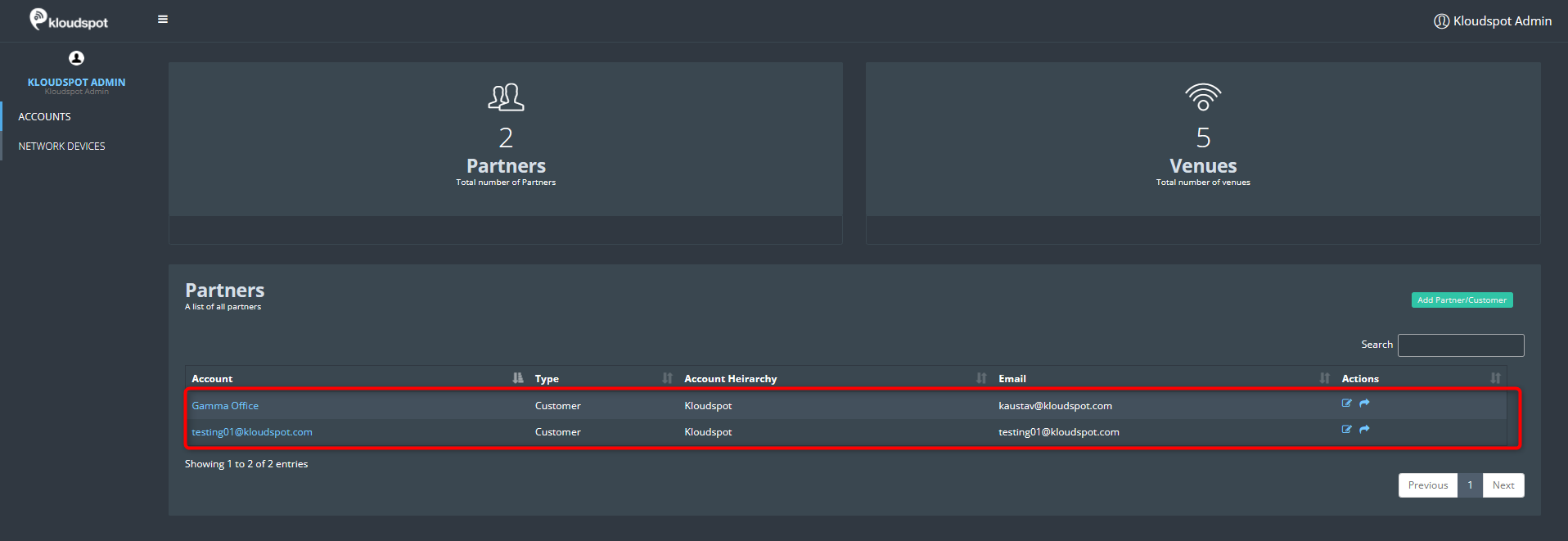
• Account: Choose the appropriate account where the KloudController needs to be added.
• Venues: Choose the appropriate Venue where the KloudController needs to be added.
• Once the KloudController is onboarded, the required licenses must be provided by the Kloudspot Team to enable communication with the Kloud Manage Application.
The Kloudspot Team requires the MAC Address of the controller for license provisioning.
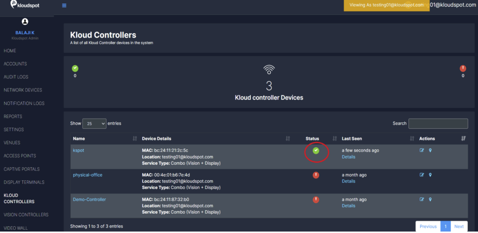
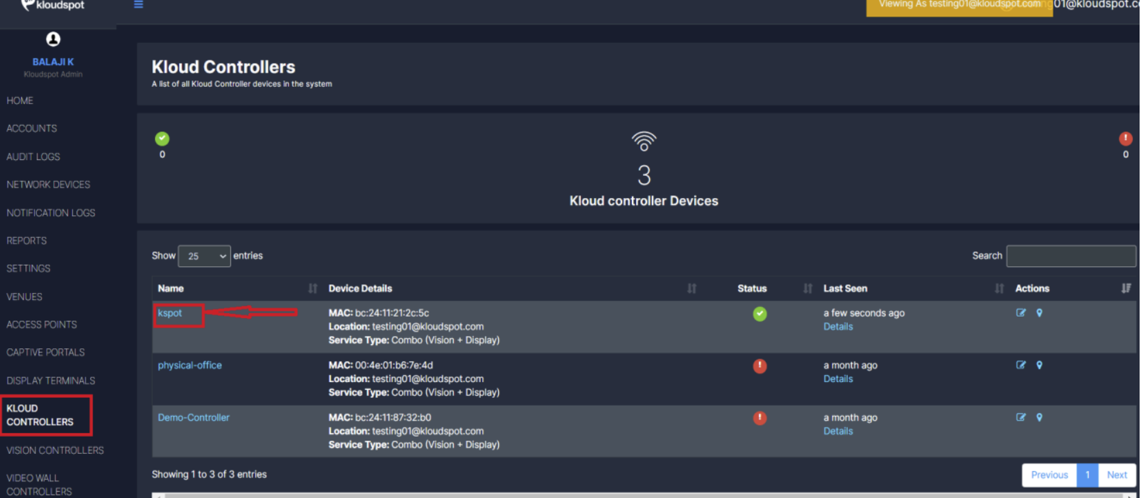
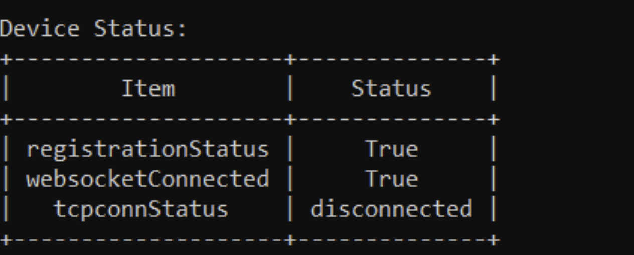
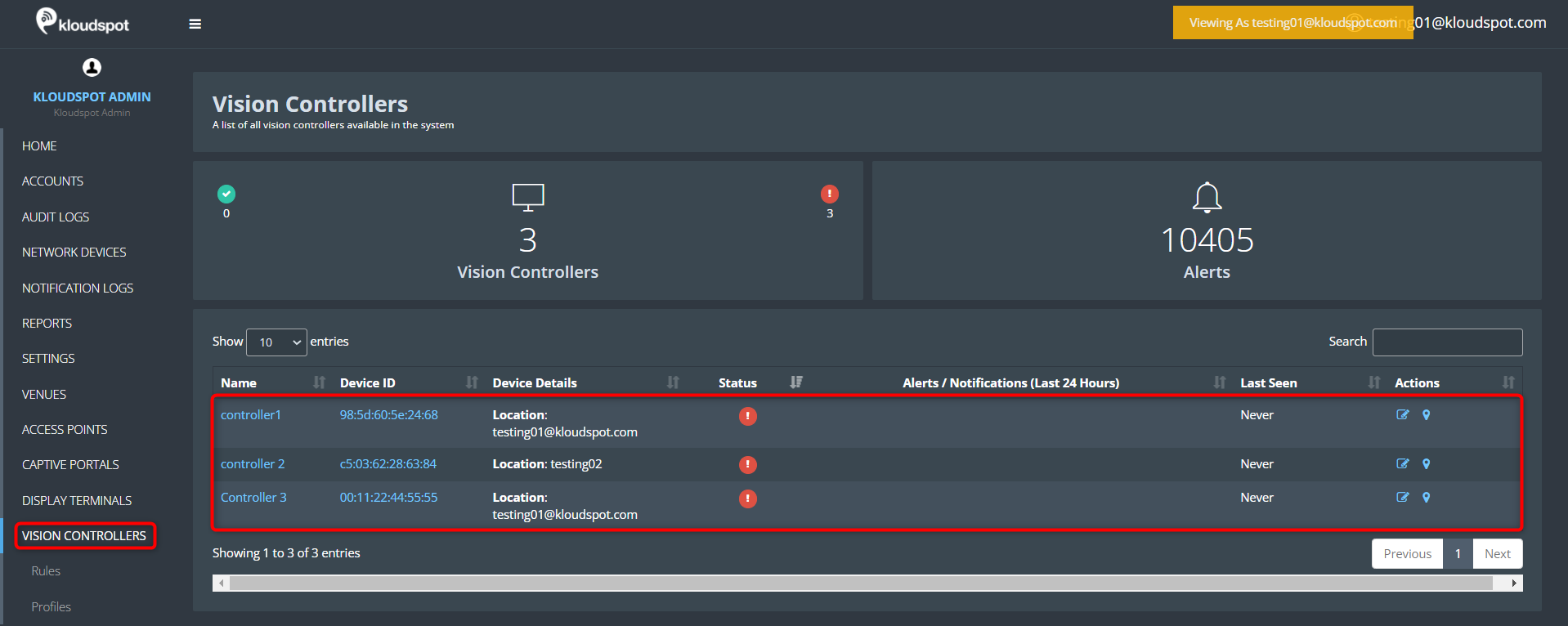
After the license is provisioned, users can check the connectivity status:
Green Status → Controller is Online.
Red Status → Controller is Offline.
In this section, we will guide you through the process of adding and configuring cameras within the KloudVision platform. By following the step-by-step instructions provided, you will seamlessly bring your cameras online, enabling them to contribute to the generation of actionable analytics.
From defining regions of interest (ROIs) to adjusting camera settings for optimal performance, the Camera Setup and Configuration process empowers you to customize your surveillance network according to your specific requirements.
Subsections of Camera Setup and Configuration (Intel)
Adding Cameras
In this section, we will guide you through the smooth incorporation of cameras into KloudVision. Incorporating cameras is more than just a physical setup; it symbolizes the merging of advanced technology and thoughtful strategy to establish a unified network of vigilant observers.
Refer to the Camera Specifications document to select the appropriate camera for your needs.
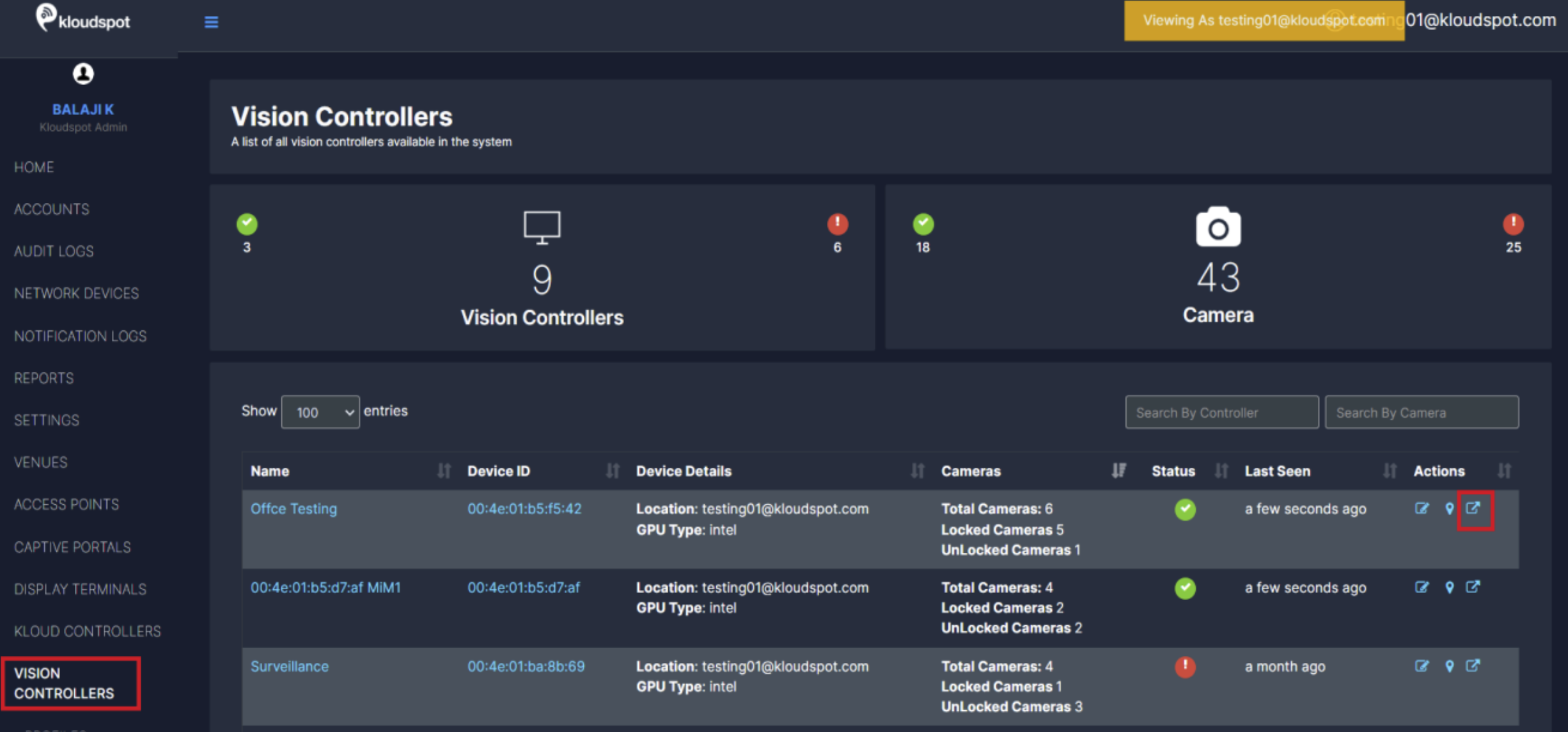
Once you have connected the controller, the next thing you need to do is to add the cameras to it. To do so, open the controller to which you want to add the camera.
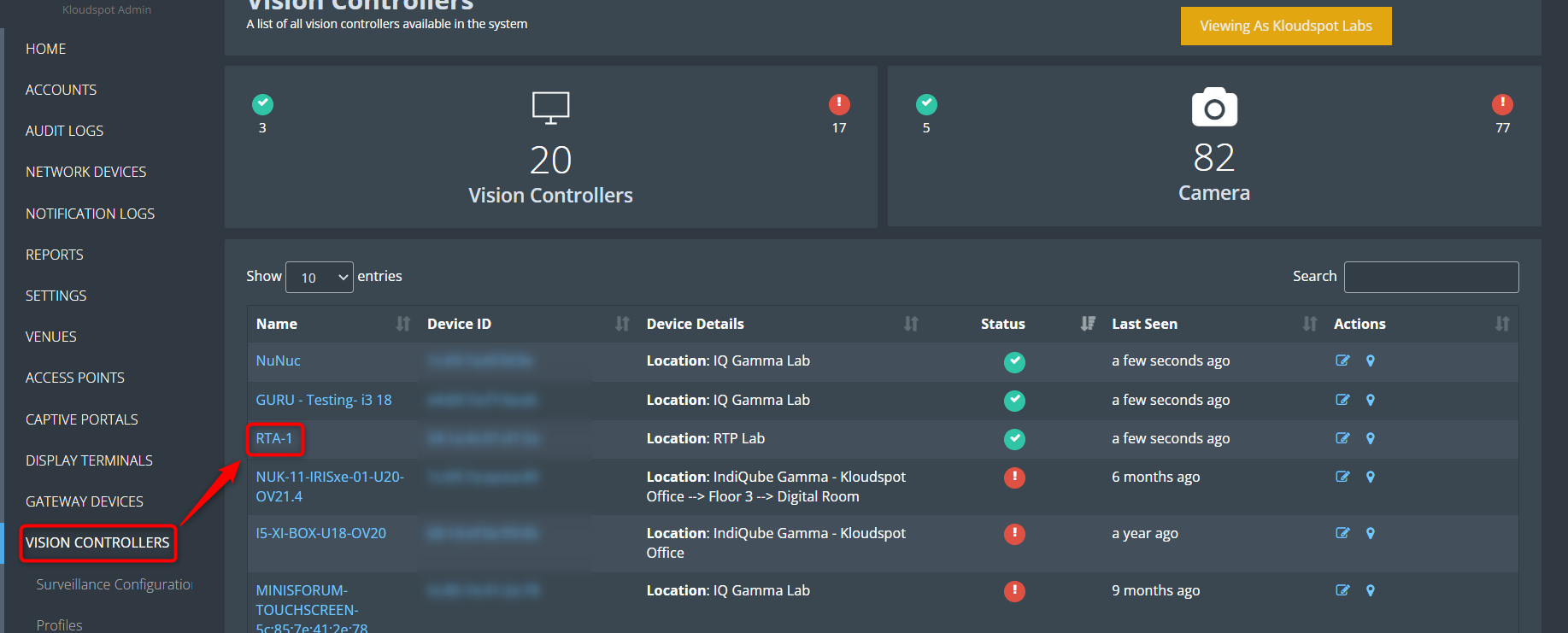
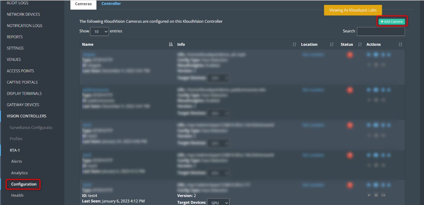
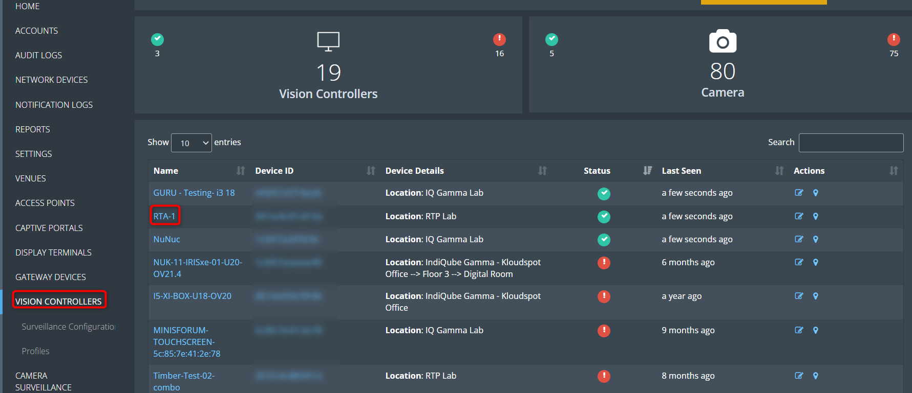
Navigate to VISION CONTROLLERS > Open the desired controller.
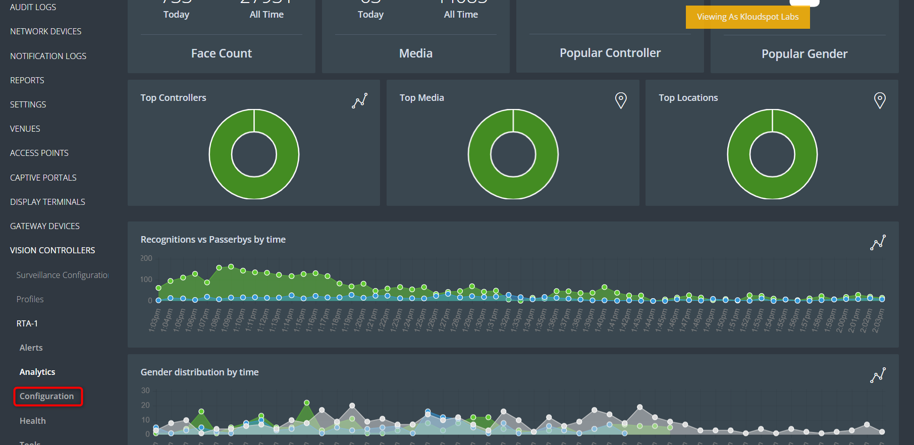
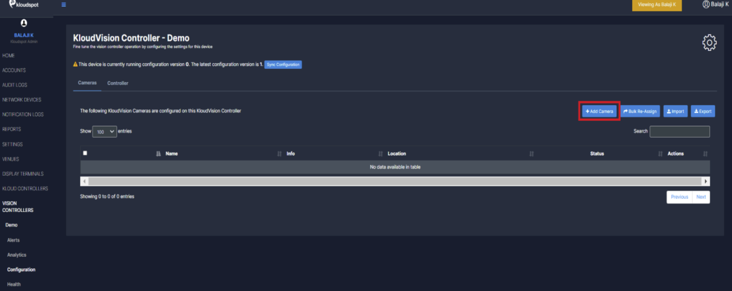
Then click on the Configuration button from the left menu bar.
In the window that opens click on the +Add Camera button.
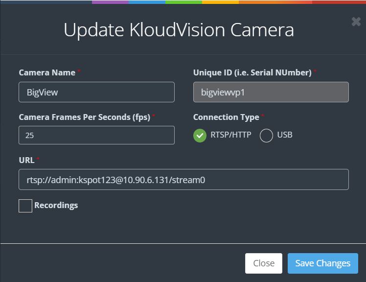
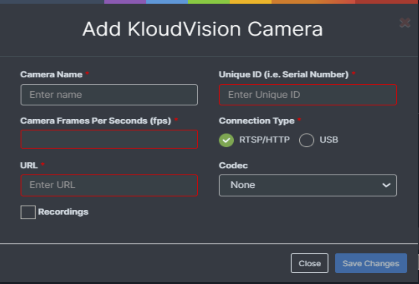
Enter the following in the popup window that opens and click the Save Changes button.
Name your camera and enter a serial number.
Choose the connection type (RSTP or USB). (Real-time streaming protocol)
If you choose, RTSP (Real-time streaming protocol) you will need to enter the URL you will link your camera feed from.
Create Profiles
This section of our guide delves into the realm of KloudVision Profiles, a dynamic tool that enables you to create and manage distinct profiles for different scenarios, locations, or requirements. By creating a profile you can avoid adding the same configuration to multiple cameras.
Follow the steps below to add a profile.
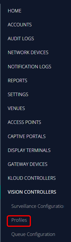
Click the Profiles button from the menu.
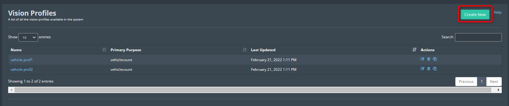
Window containing the profiles will open. Click Create New button from the top right corner.
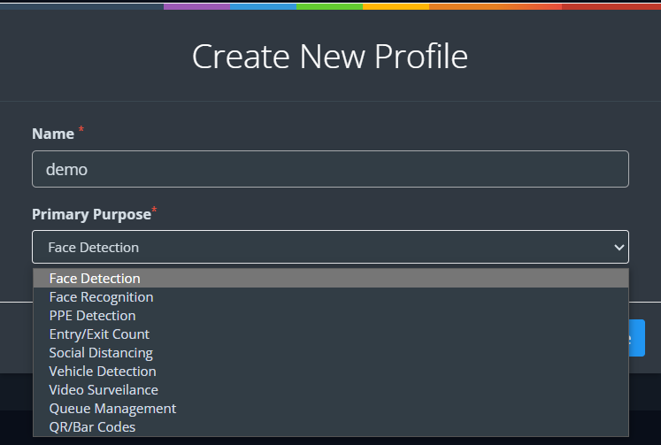
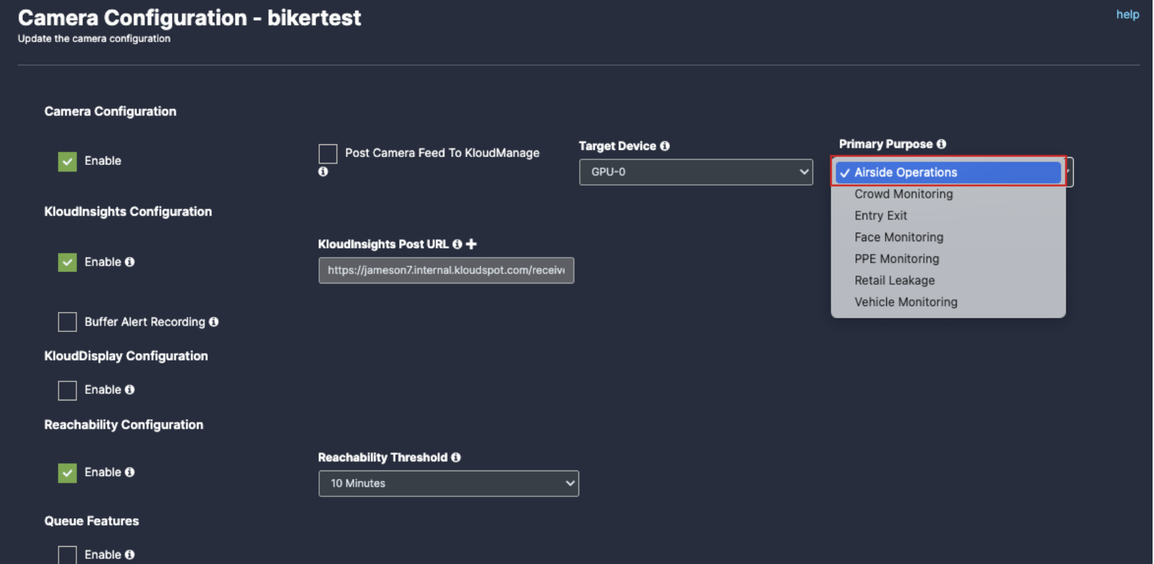
Enter the profile name and select the primary purpose from the dropdown menu.
Face Detection: Used to detect the face and related parameters of visitors.
Face Recognition: Used to configure FRS (face recognition system) using KloudInsight.
PPE Detection: Used for Personal Protective Equipment-related use cases.
Entry/Exit count: Used to calculate the number of visitors.
Social Distancing: Used to determine whether visitors maintain a social distance.
Vehicle Detection: Used to detect the vehicle and related parameters.
Video surveillance: Used to configure video surveillance.
Queue Management: Used to configure queue management.
QR/Bar Codes:
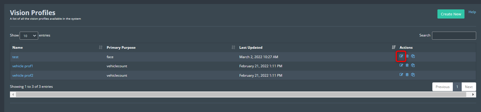
Once the profile is created it will be displayed in the profile list.
Click the Edit button to configure the profile.
Each profile type offers specific configuration options. Refer to the corresponding sections for detailed guidance on configuring different profile types:
Refer Configure Face Detection
section to configure the face detection profile.
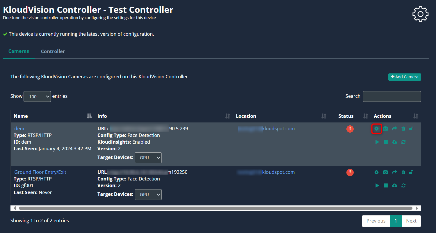
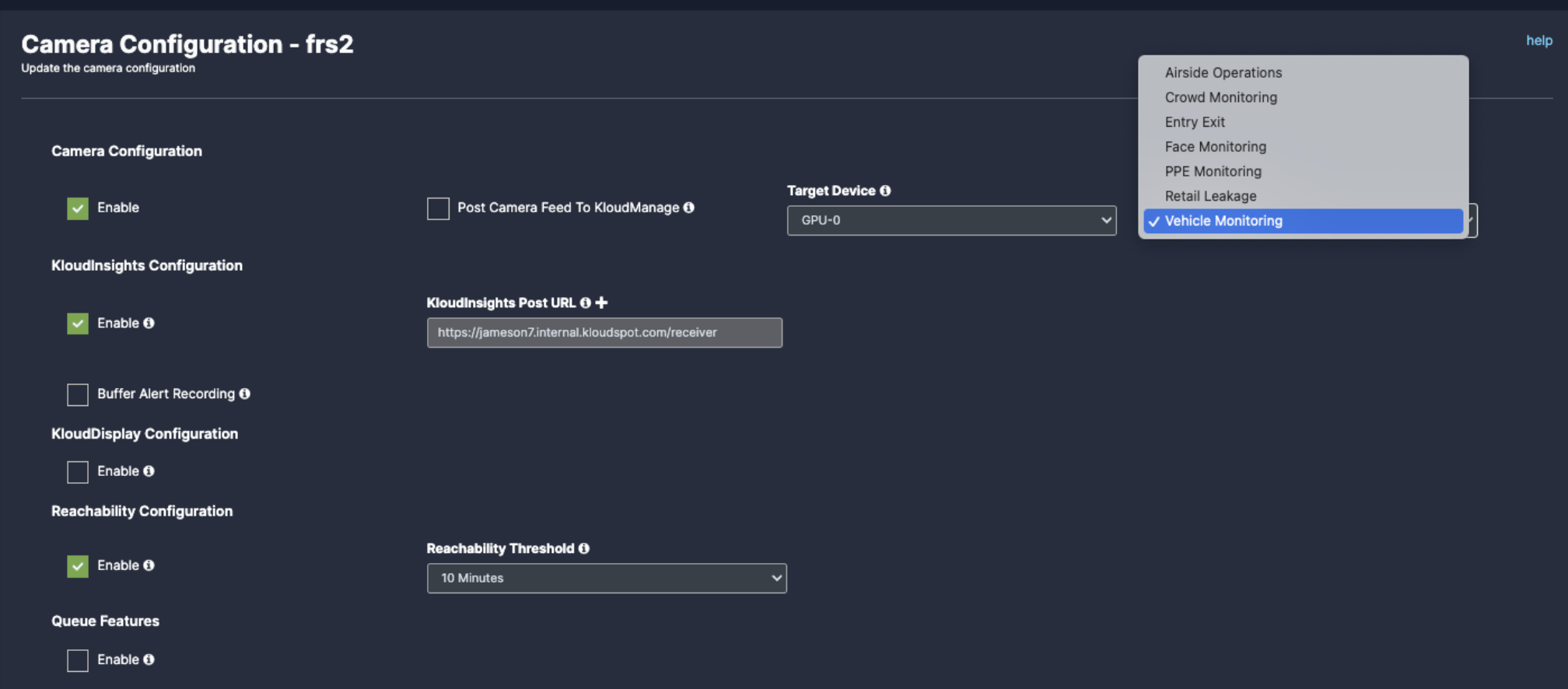
Here are the common steps to do regardless of which camera you install. You can configure the following according to your needs. To configure general camera configurations, navigate to Vision Controllers > (Select the controller).
Immediately the controller dashboard will open and click on the configuration button from the menu bar.
In the camera list that opens, click on the Configuration button next to the camera you want to configure. Immediately the camera configuration window will open.
The configurations used as common in all use cases are given below.
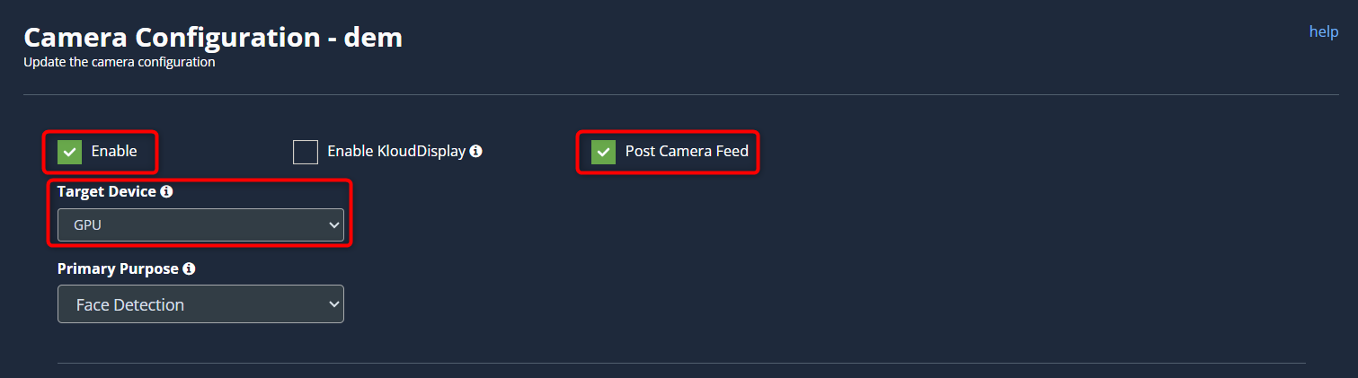
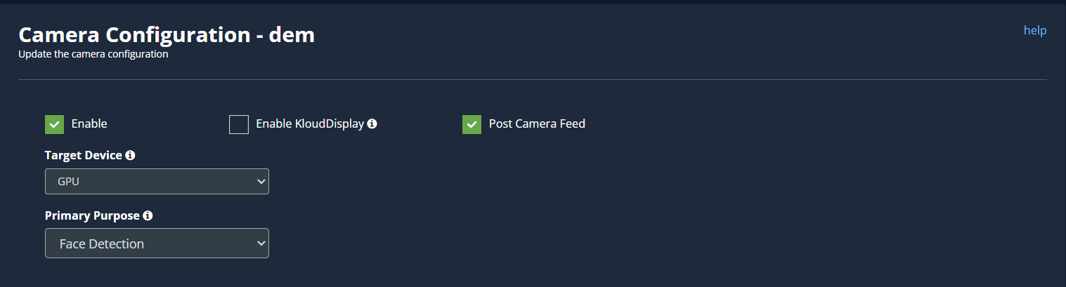
Enable: To activate any camera setup you desire, check enable checkbox.
Target device: Select the type of hardware used.
Post Camera Feed: Enable this check box if you want to get camera status in KloudManage application.
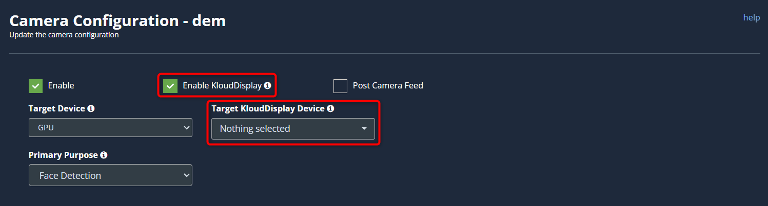
Enable KloudDisplay: Check this option to configure a KloudDisplay to react to the events generated by the camera. Click on the Target KloudDisplay dropdown to tie this camera with a KloudDisplay. Examples of this could be displaying a ‘Please wear a mask’ message on the display when the camera detects a person without a facemask.
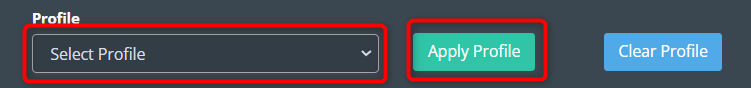
Profile:
Select the profile containing the configuration to be added from the dropdown list. Refer to the Create profiles section for more information about profile.
Note: This is useful if you are doing the same configuration on multiple cameras. Otherwise, this step can be skipped.
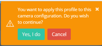
Click Apply Profile button to apply the profile. In the popup window that appears, click on the Yes, I do button.
Note: Once applied, the configuration cannot be edited later.
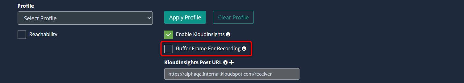
Buffer Frame For Recording:
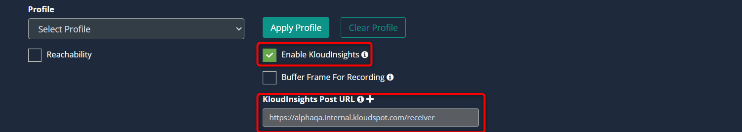
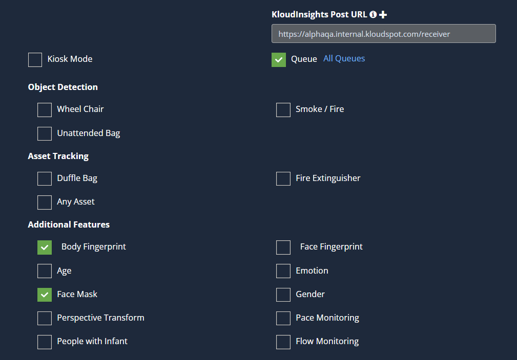
Enable KloudInsights: If you intend to share data from this camera with KloudInsights, please enable the designated checkbox. This will allow you to utilize the collected data to create new dashboards within the KloudInsights platform. Before proceeding, ensure integration between our Kloud Insights platform and KloudManage. Refer to the Integration with KloudManage section for detailed instructions on how to perform this integration.
KloudInsights Post URL : Enter your KloudInsights URL here.
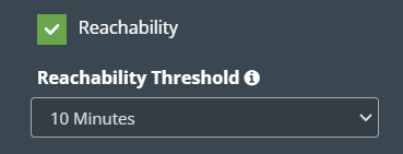
Reachability: It notifies you if the camera is inactive for an extended period. For example, If you set reachability to 10 you will get a notification if the camera is inactive for more than 10 minutes.
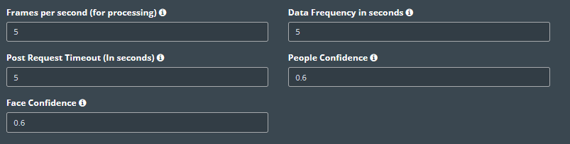
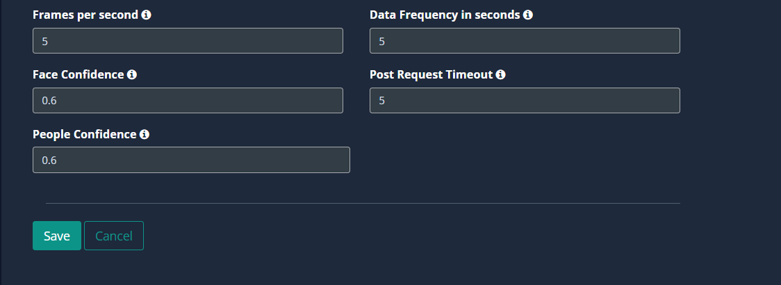
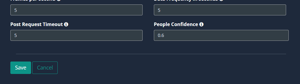
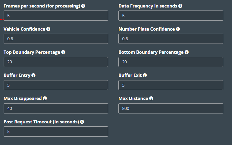
The following are the common options available in advanced settings. Values shown below are the default values for each of these options. The default values can be changed as per configuration required.
Frames per second (for processing): These are the number of frames used by Vision Controller every second for data processing. KloudVision does not use all the frames emitted from the camera in a second. Higher values provided in this field may increase CPU/GPU usage.
Data Frequency in seconds: This value indicates how long Vision controller aggregates data before sending it out to KloudInsights. A lower value may increase the data frequency and result in a faster response. A higher value results in a delayed response.
People confidence: This value is the probability that a detected shape on camera is a person. Higher values may fail to detect people. Lower values may detect objects that are shaped as people.
Face Confidence: This value is the probability that a detected shape on camera is a face. Higher values may fail to detect faces. Lower values may detect objects that are shaped like faces.
Post Request Timeout (in seconds): This value indicates how long KloudVision waits and retries to send the payloads out to KloudInsights until it reaches the preset timeout period.
Face Detection Configuration
If you want to configure any of the following use cases on your camera, you can configure it using the Face detection feature.
Queue management
Detection
Duffle Bag tracking
Fire Extinguisher tracking
Face fingerprint detection
Emotion detection
Gender detection
Pace monitoring
Flow monitoring
Age detection
Face Mask detection
Perspective Transform
Detecting People with Infant
Before you begin configuring the use cases, you should first configure the camera’s general configuration. Refer to the General Camera Configuration section for instructions.
Then, select the Face Detection from the dropdown list.
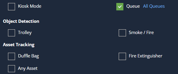
Next, scroll down and choose your preferred use cases. You can choose multiple use cases.
The next step is to plot the ROI on the camera feed. This is necessary for the Queue management feature, as well as in other use cases where Kiosk mode is enabled. Otherwise, it’s optional. Refer to Queue Management section to know how to configure a Queue. Refer to the Draw ROI (region of interest) on the camera frame section to learn how to add an ROI to the camera feed.
Kiosk Mode: Kiosk mode is mainly developed for vending machines where we will be displaying contextual advertising based on the demographics of the people and it also has additional options for choosing the detection range and prominent where it will consider the demographics of the first person in a queue.
Some use cases require additional values; there will be a default value. If you wish to change it, you can. Refer to the Configuring the Face Detection Parameters section to learn what this is and how to change it.
Click the Save button to save the configuration.
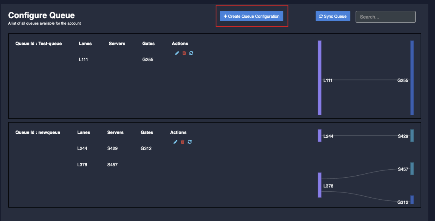
Queue management
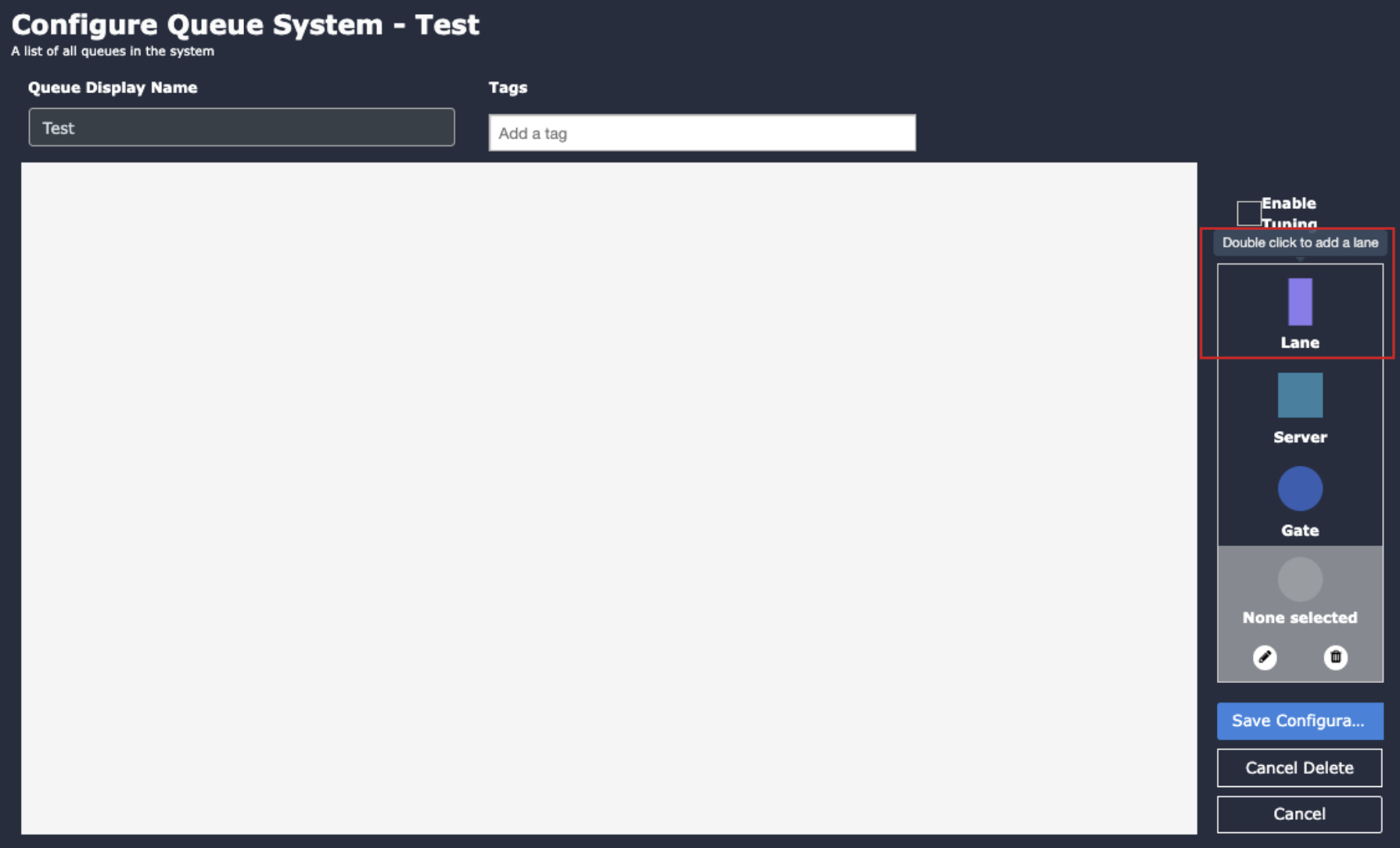
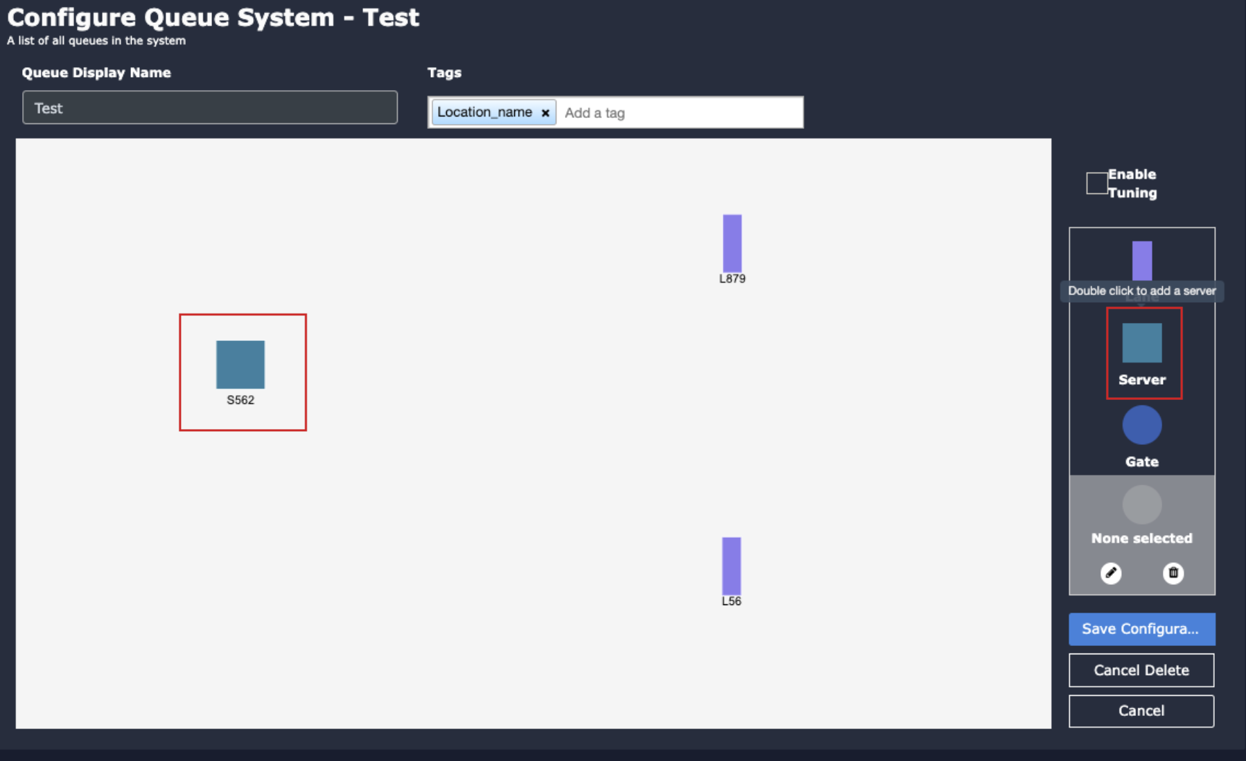
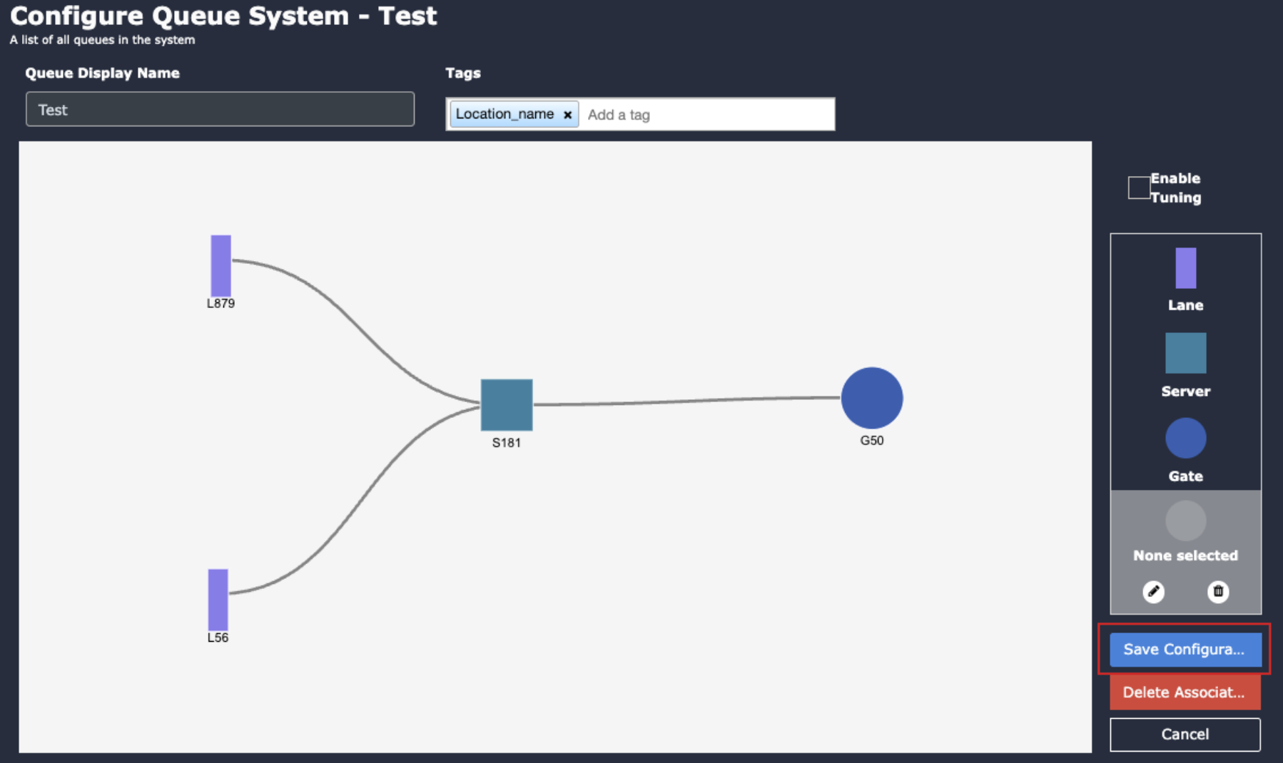
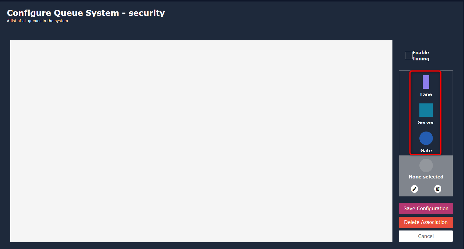
Configuring queue monitoring involves defining Regions of Interest (ROIs) to focus on specific sections of a queue, such as the lane area, server area, and exit gate. This document outlines the steps to configure queue monitoring to a camera for efficient surveillance and monitoring.
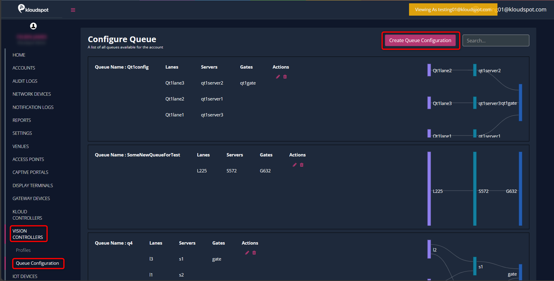
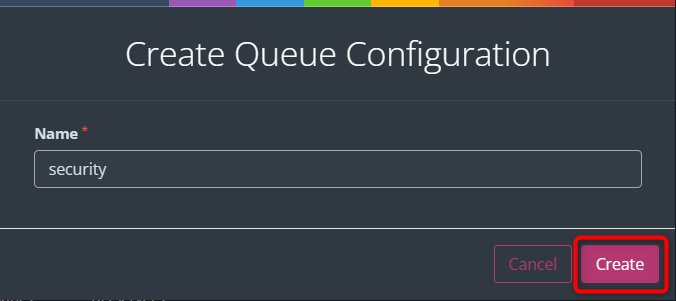
Ensure that you have already created a queue. Refer to the “Queue Creation
" document for instructions on how to create a queue.
Note: It is important to note the specific section that the configured camera is targeting. There are instances where a single camera encompasses all three sections. Alternatively, a queue might require configuration with multiple cameras. The following outlines the process for configuring a lane using a single camera, and this logic can be applied to configure multiple cameras.
If you want to enable this feature, Check the Queue checkbox.
Click All Queues button to view the currently available queues.
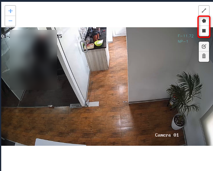
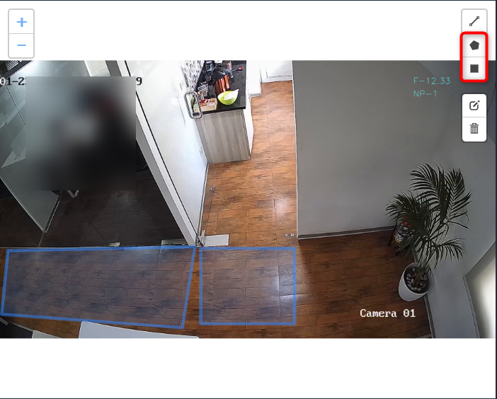
Next, draw the ROI in the camera frame. This is mandatory for Queue management.
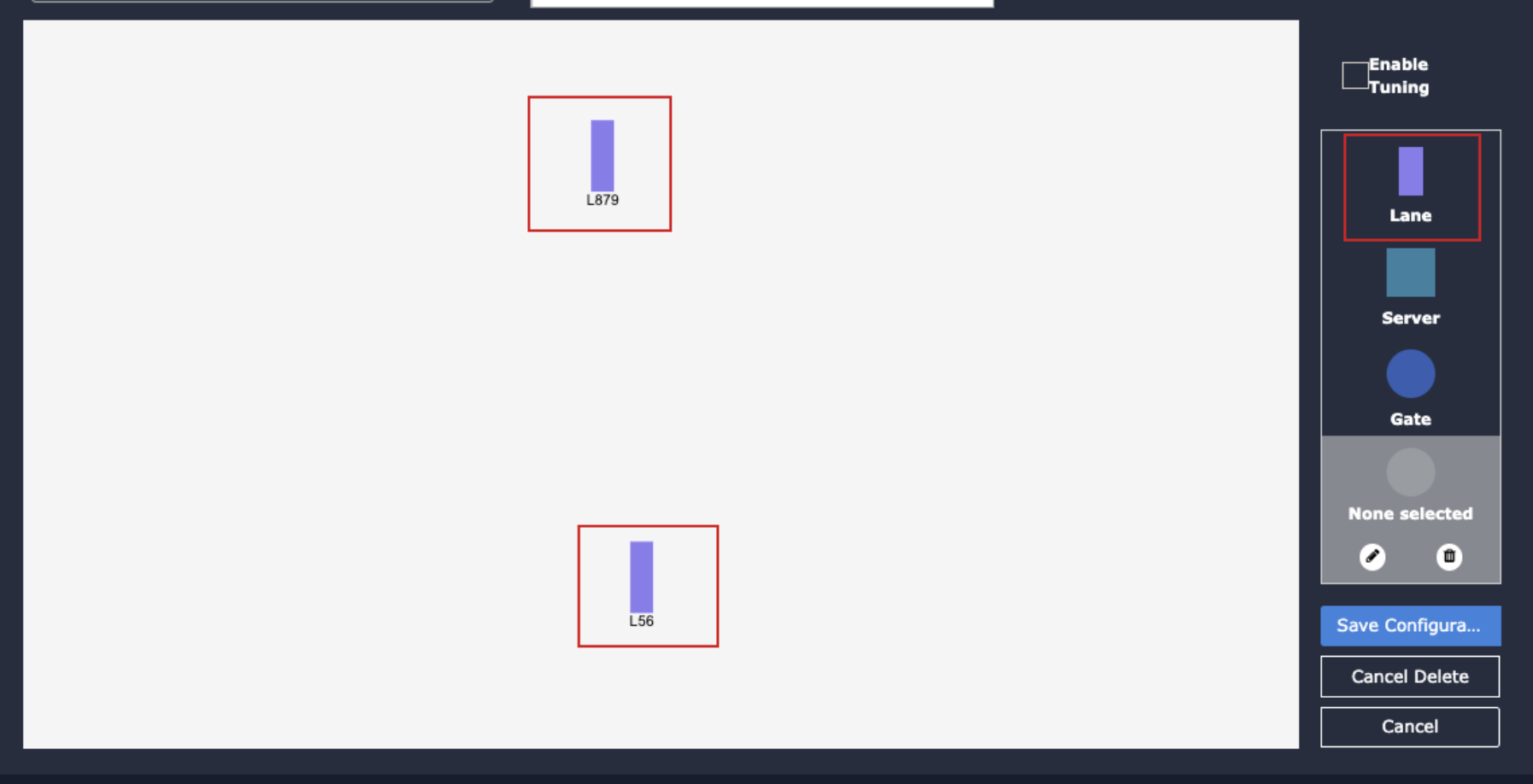
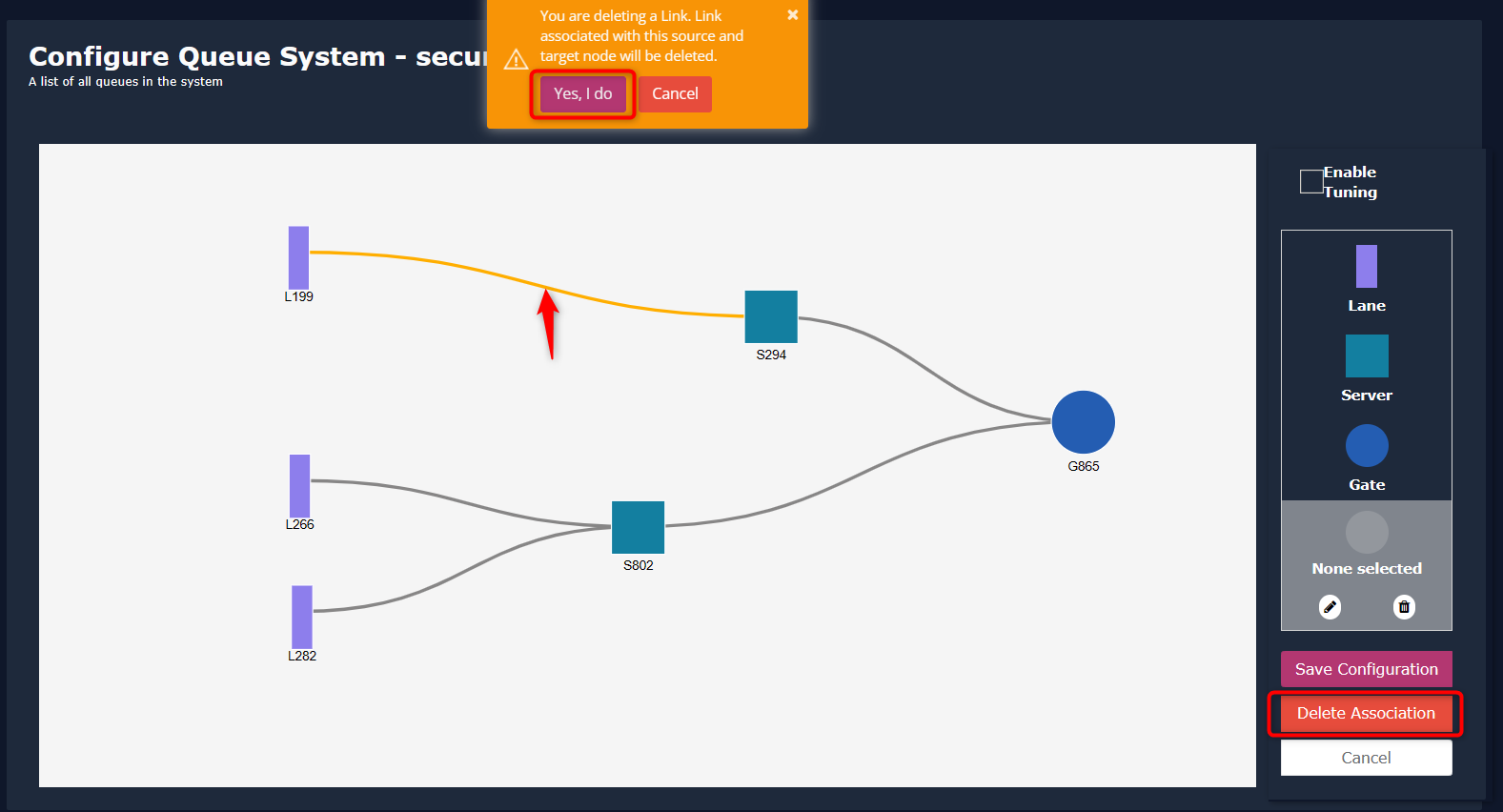
Configuration Process
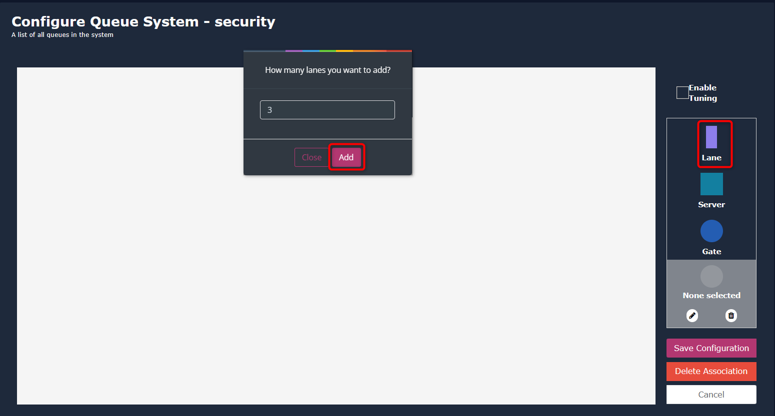
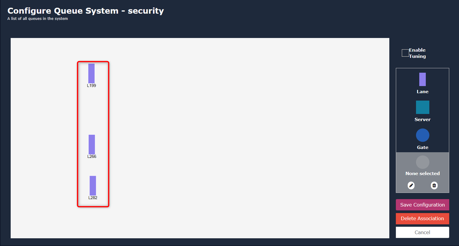
Marking the Lane Area
Draw ROI for Lane Area:
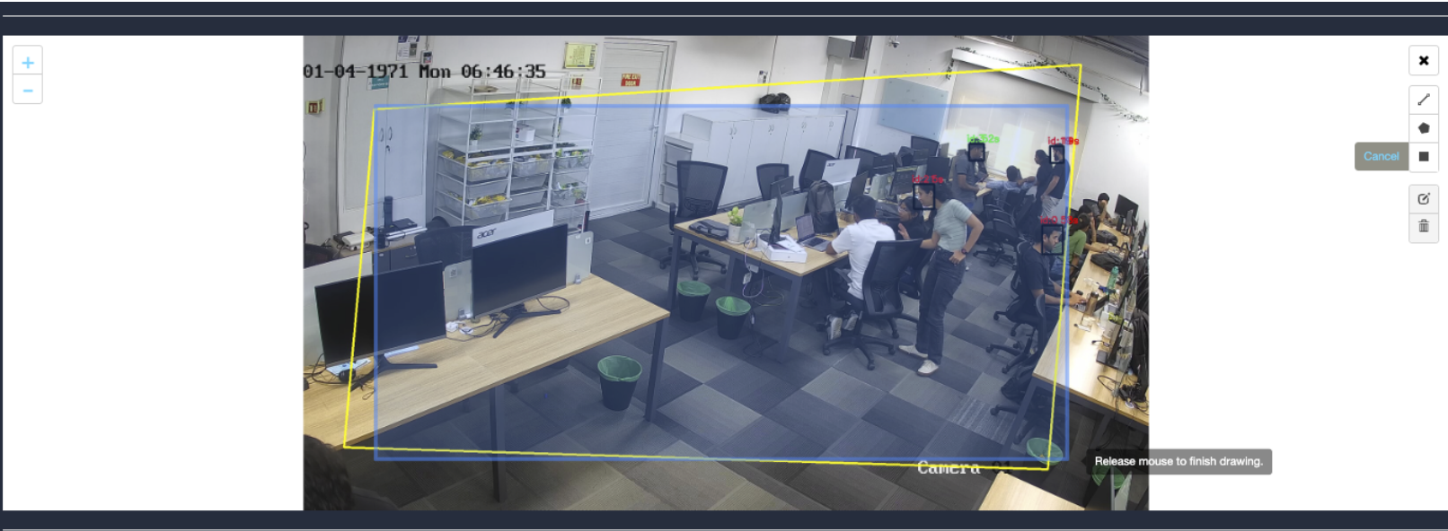
Using a polygon or rectangle tool, draw a Region of Interest (ROI) on the camera feed at the locations corresponding to the lane area of the queue.
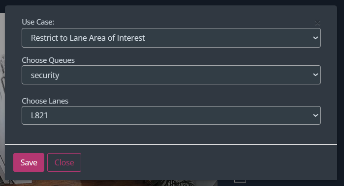
Configure Lane Area:
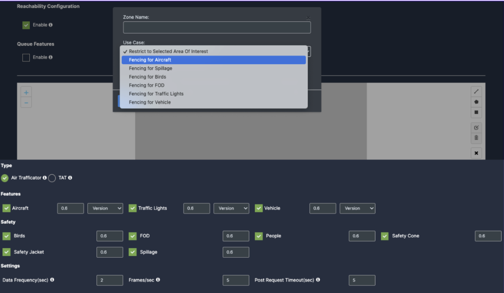
In the popup window that appears after drawing the ROI, navigate to the Use Case column.
Select Restrict to Queue Area of Interest from the options.
Choose the queue you created earlier from the Choose Queues dropdown list.
Select the specific lane you are configuring from the Choose Lanes dropdown list.
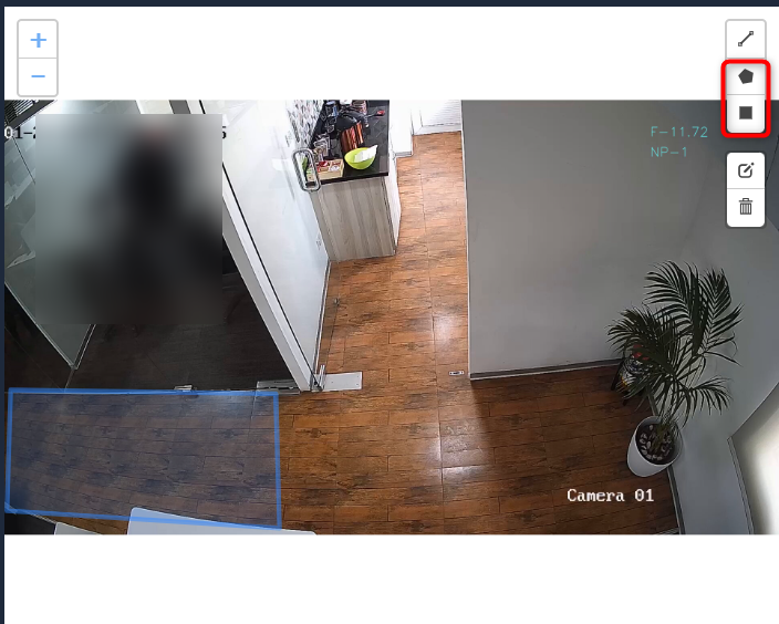
Click the Save button to save the configuration.
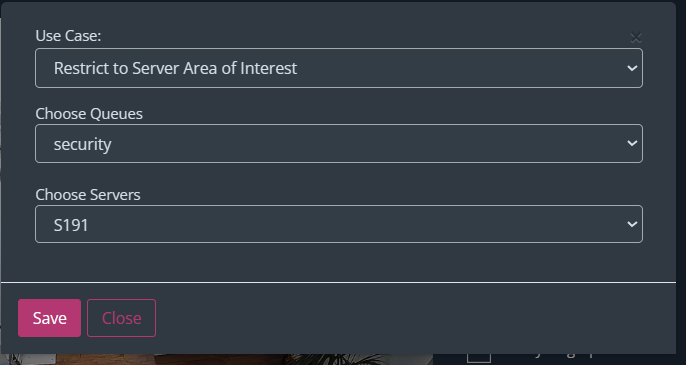
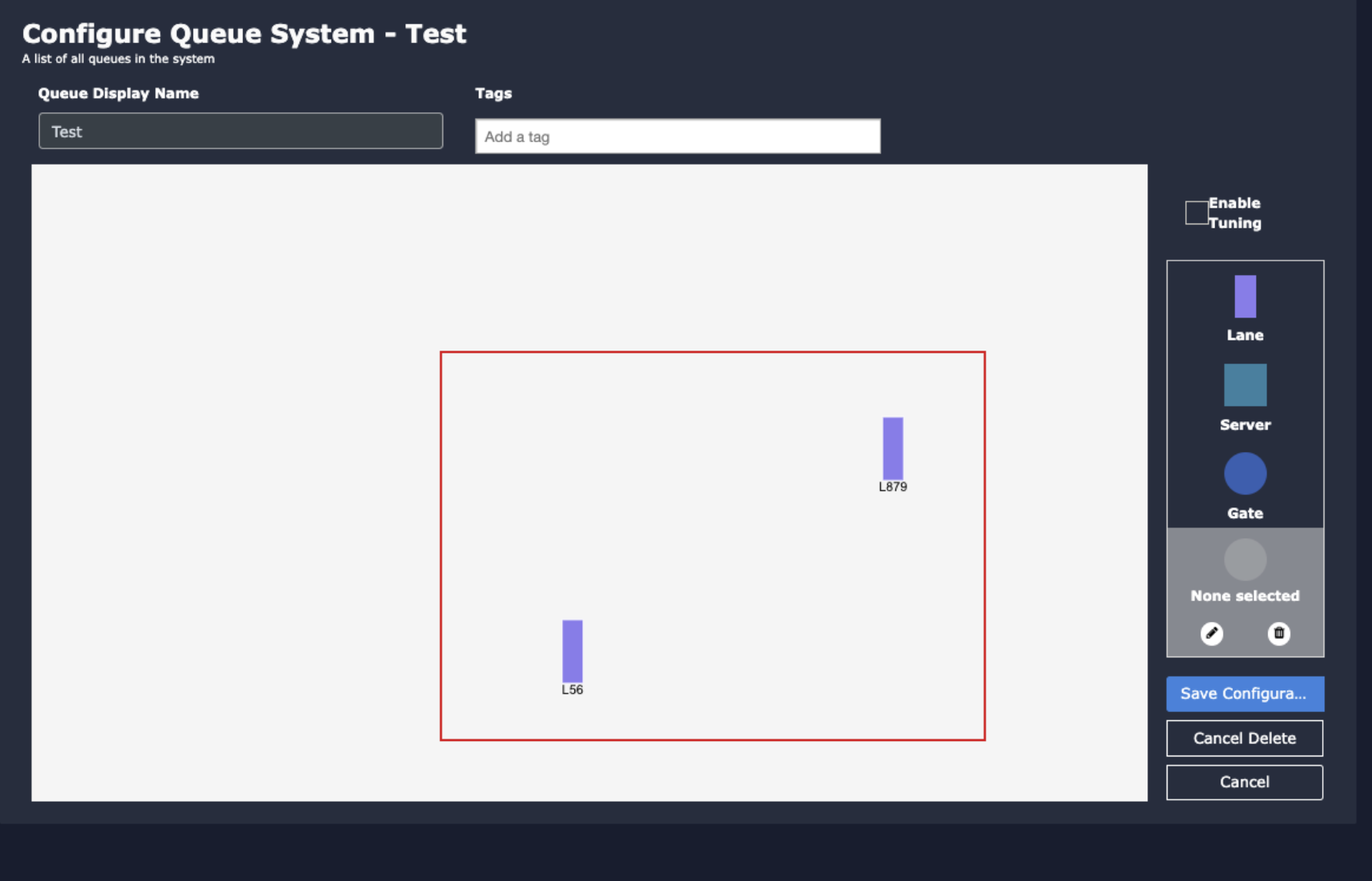
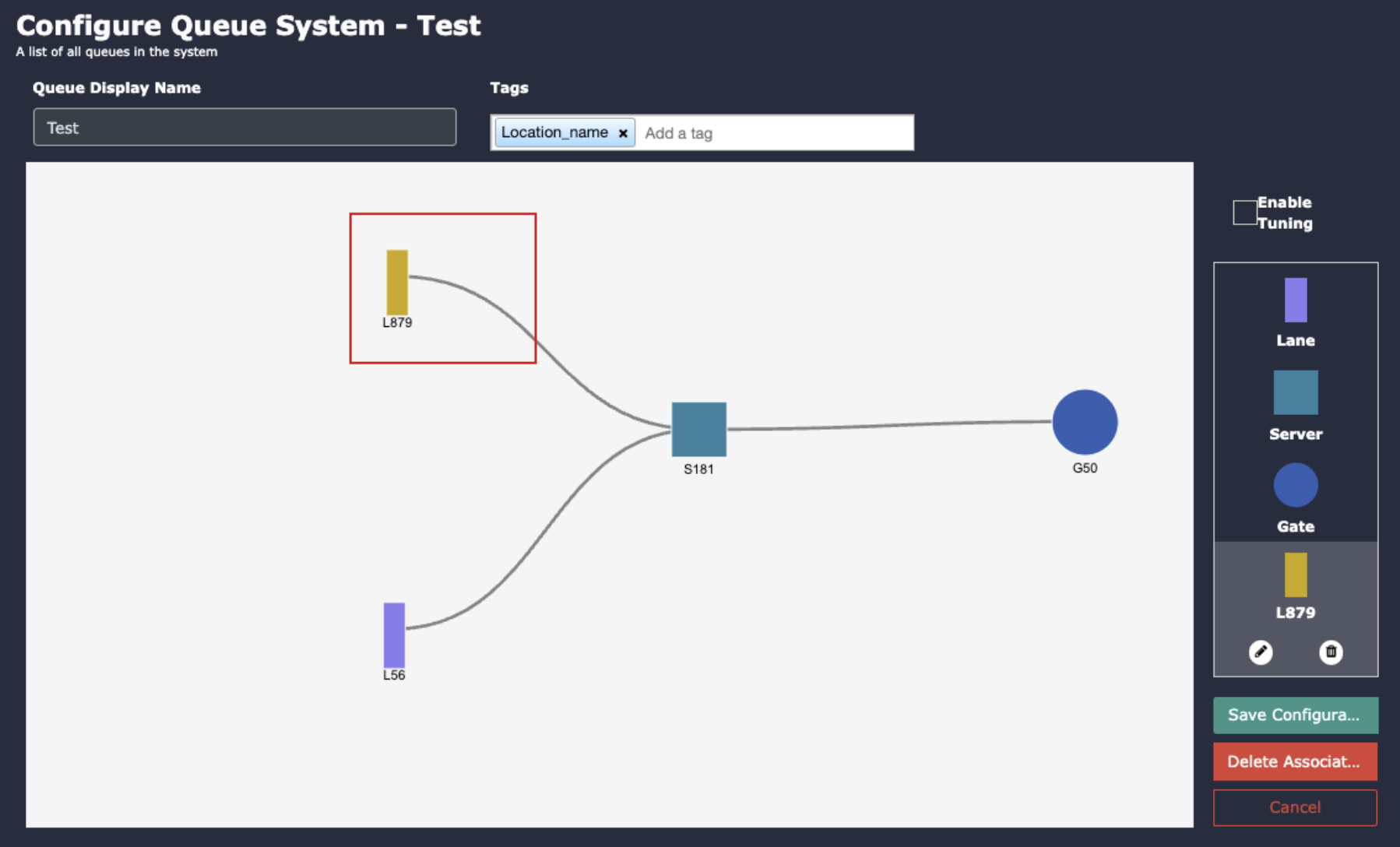
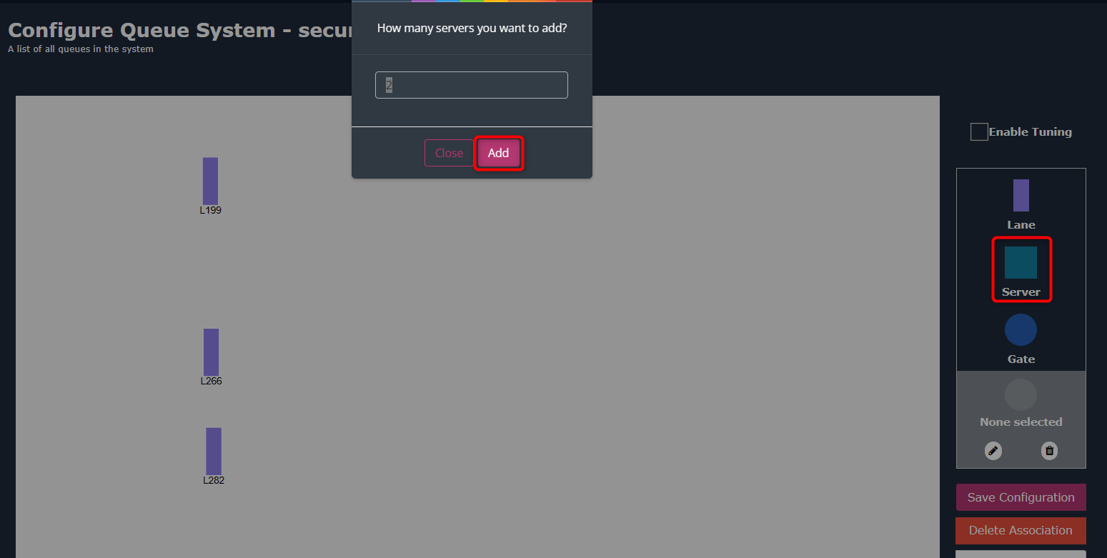
Marking the Server Location
Draw ROI for Server Area:
Draw another ROI using the polygon or rectangle tool at the places where the server area appears in the camera feed.
Configure Server Area:
In the popup window, choose Restrict to Server Area of Interest from the Use Case column.
Select the queue from the Choose Queues dropdown list.
Choose the server area you are configuring from the Choose Servers dropdown list.
Click the Save button to save the configuration.
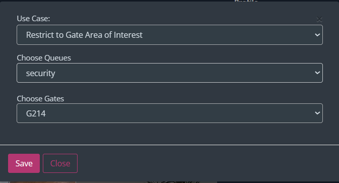
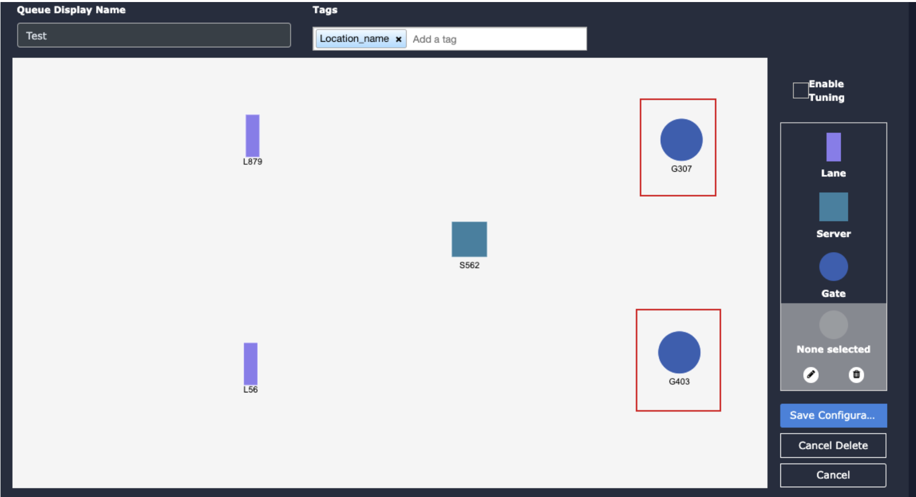
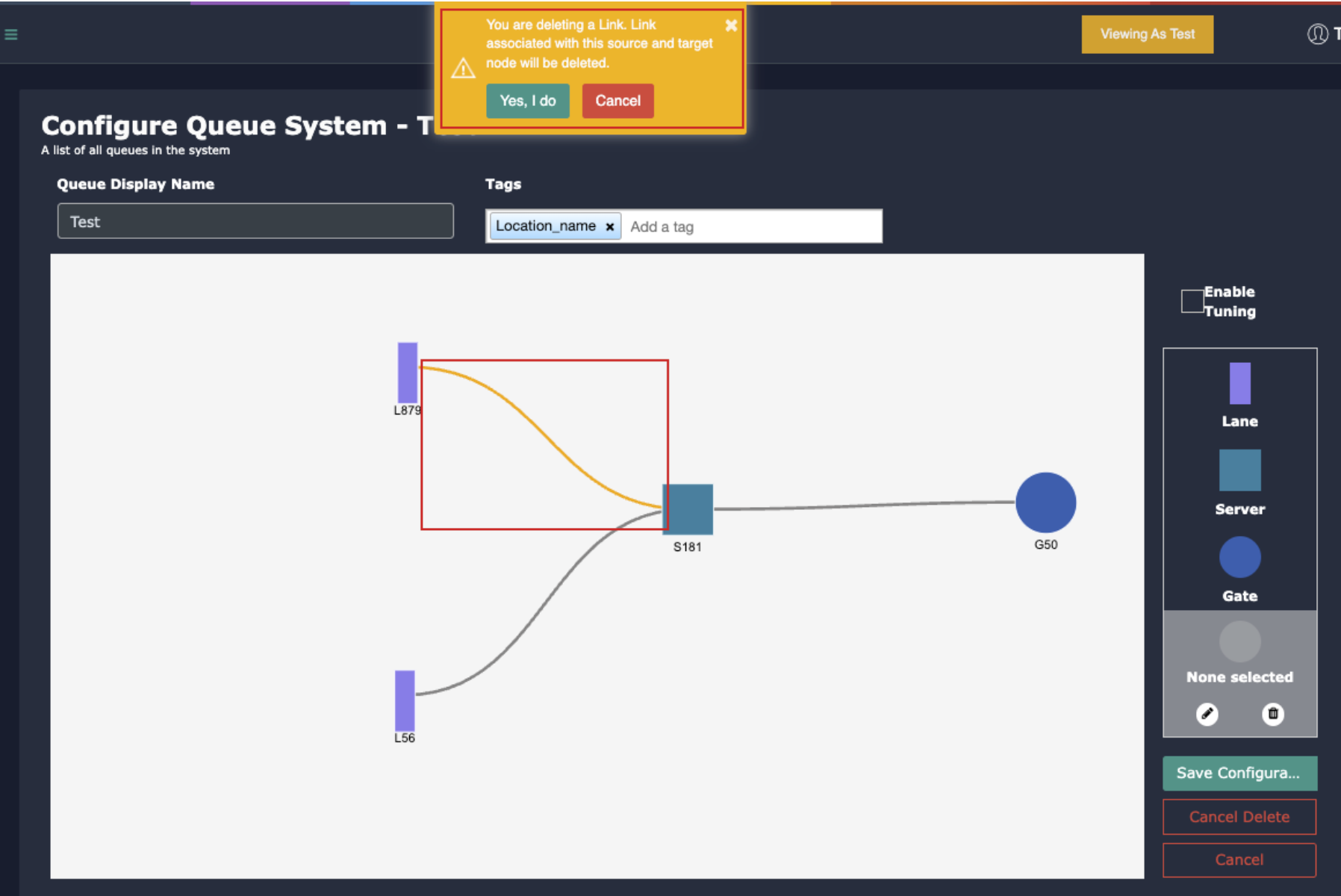
Marking the Exit Gate Location
Draw ROI for Exit Gate Area:
Draw an additional ROI for the exit gate area using the polygon or rectangle tool.
Configure Exit Gate Area:
In the popup window, select Restrict to Gate Area of Interest from the Use Case column.
Choose the queue from the Choose Queues dropdown list.
Select the gate area you are configuring from the Choose Gates dropdown list.
Click the Save button to save the configuration.
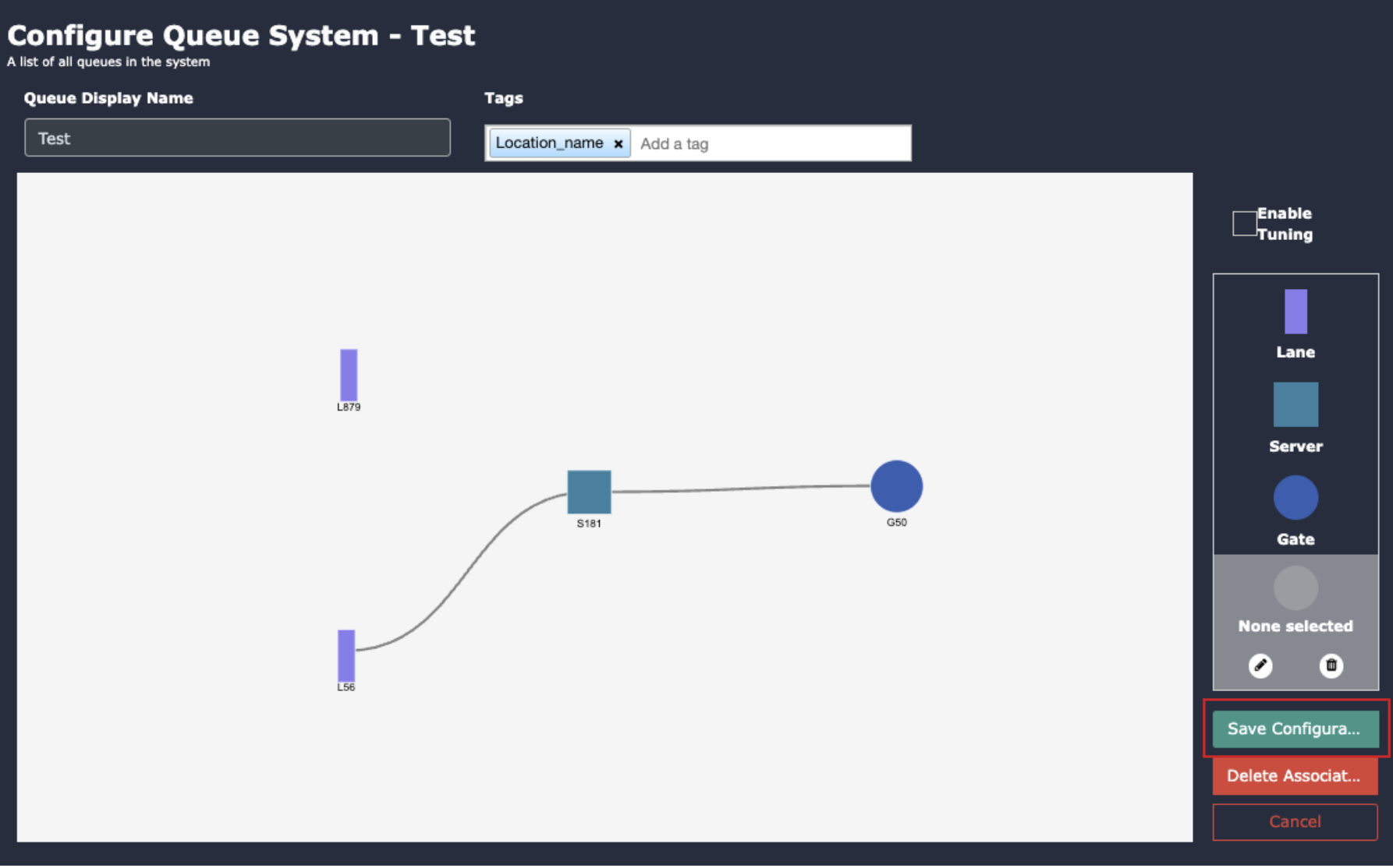
Save Camera Configuration
Scroll down to find the general camera settings.
Click the Save button to save the overall camera configuration.
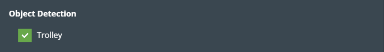
Object Detection
It is useful for tracking a Trolly and immediately reporting if its speed is slower than normal.
This feature helps determine whether customers are having difficulty using the trolley and assists them if they are.
For example, airports, supermarkets, hospitals, etc.
If you want to enable this feature, check the Trolly checkbox.
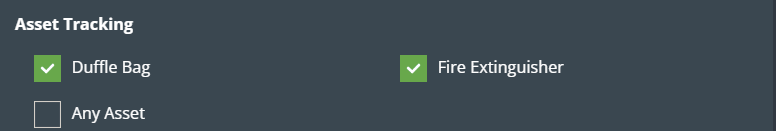
Asset Tracking
Kloudvision asset tracking involves using cameras to monitor the location and movement of valuable assets such as Duffle Bag, Fire Extinguishers, and other assets.
Duffle Bag: It helps in the tracking of duffle bags at any place. It detects and reports duffle bags displacement in real time.
Fire Extinguishers: It helps in the tracking of Fire Extinguishers at any place. It detects and reports Fire Extinguishers displacement in real time.
Any assets: it helps to track small assets. It detects and reports assets displacement in real time.
Check the checkbox if you want to enable any of these features.
Draw ROI (region of interest) on the camera frame.
ROI in camera frames can help to improve efficiency, accuracy, and reduce storage requirements.
ROI must be added if kiosk mode is enabled. Otherwise, it is optional. If ROI is not added, the model will detect the entire frame.
For face detection, ROI can be drawn in two ways.
Using the polygon tool
Using the rectangle tool.
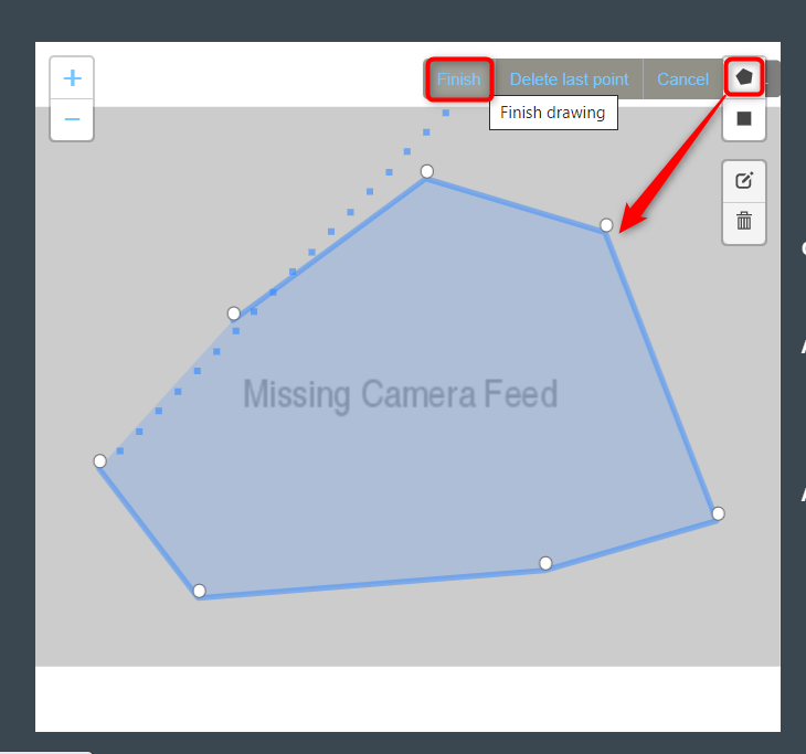
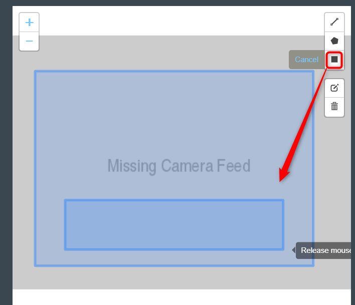
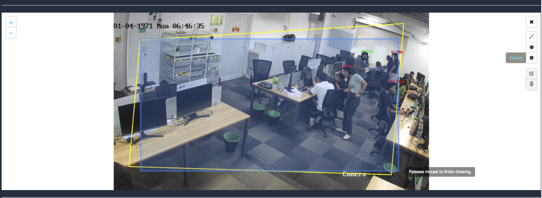
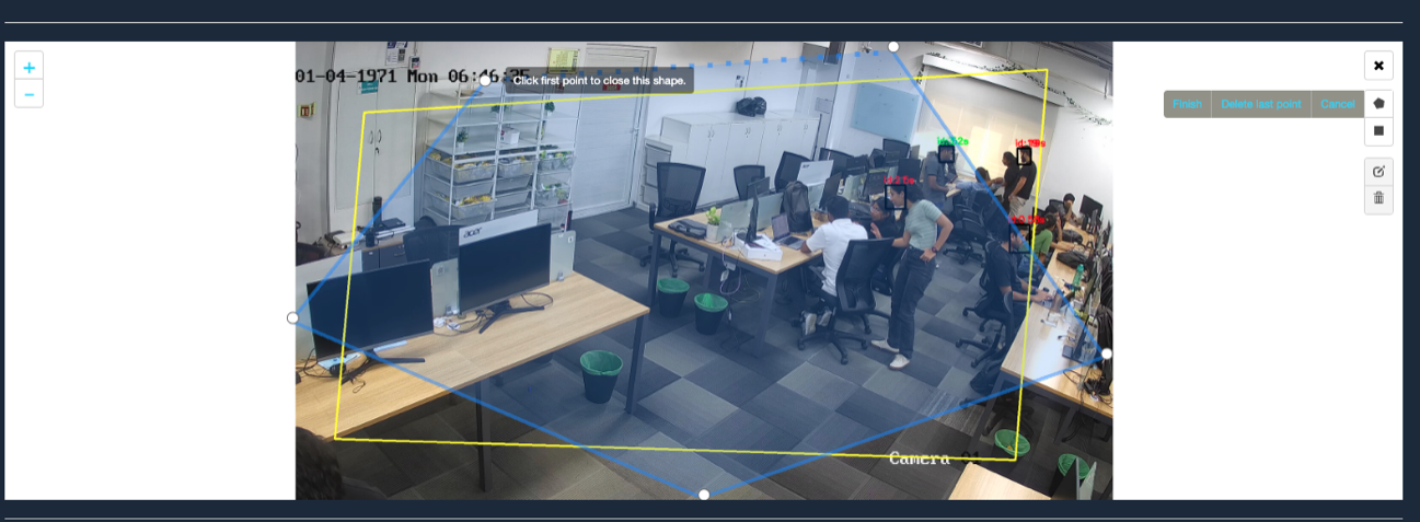
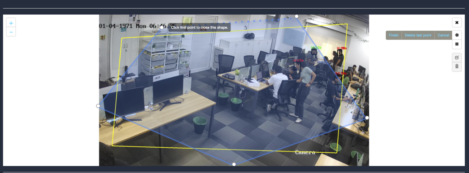
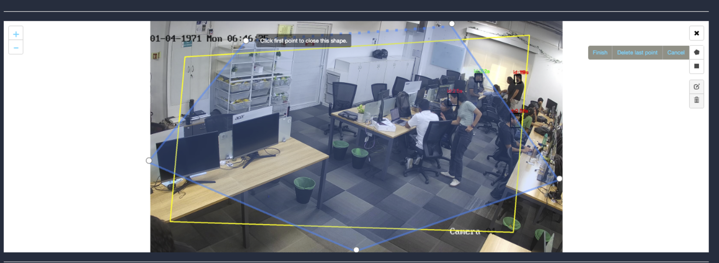
Draw ROI using the Polygon tool.
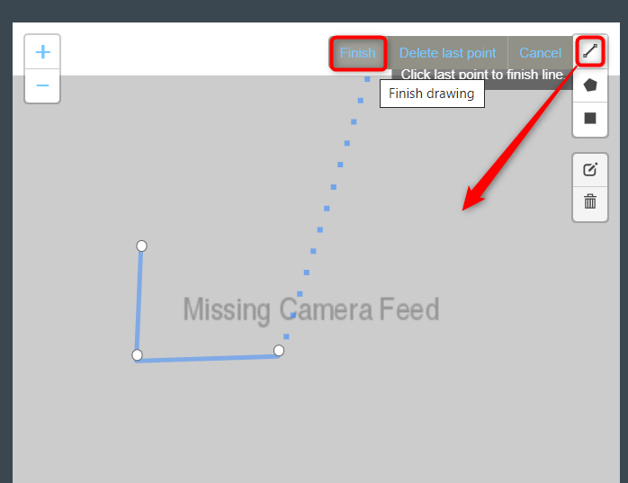
Click on the Polygon tool button from the camera frame.
Then connect the dots and draw the polygon in the space where you want to draw the ROI. It should have more than 2 points.
After drawing, click the Finish button to complete the drawing.
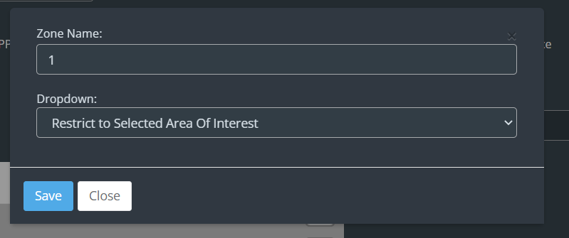
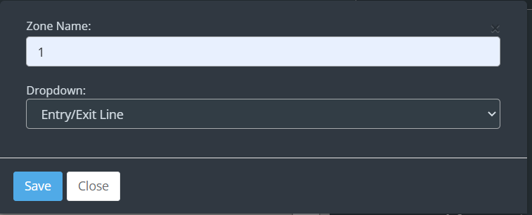
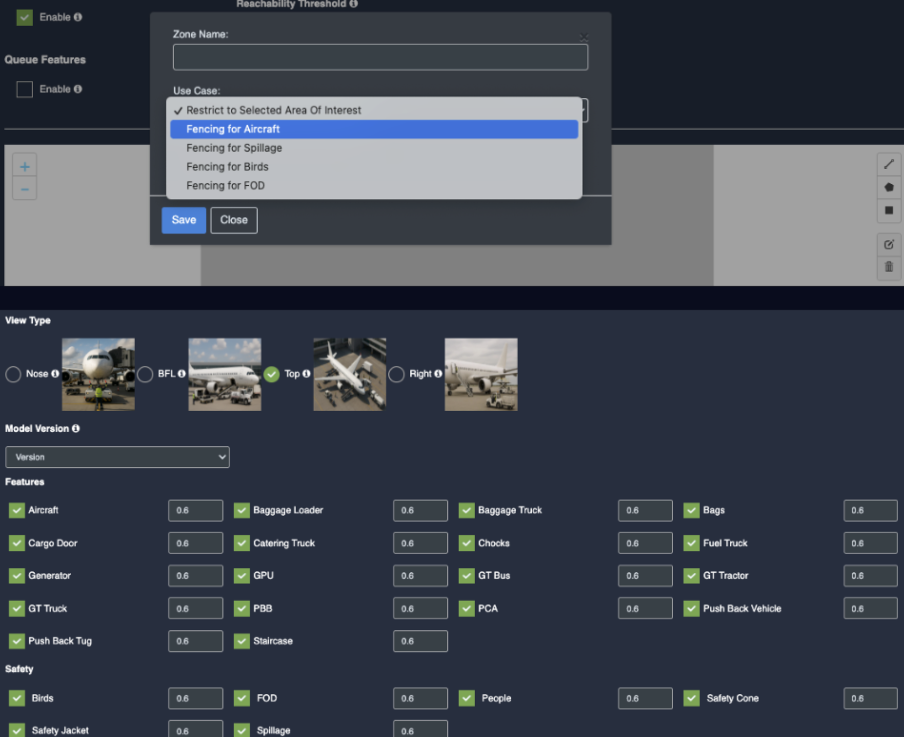
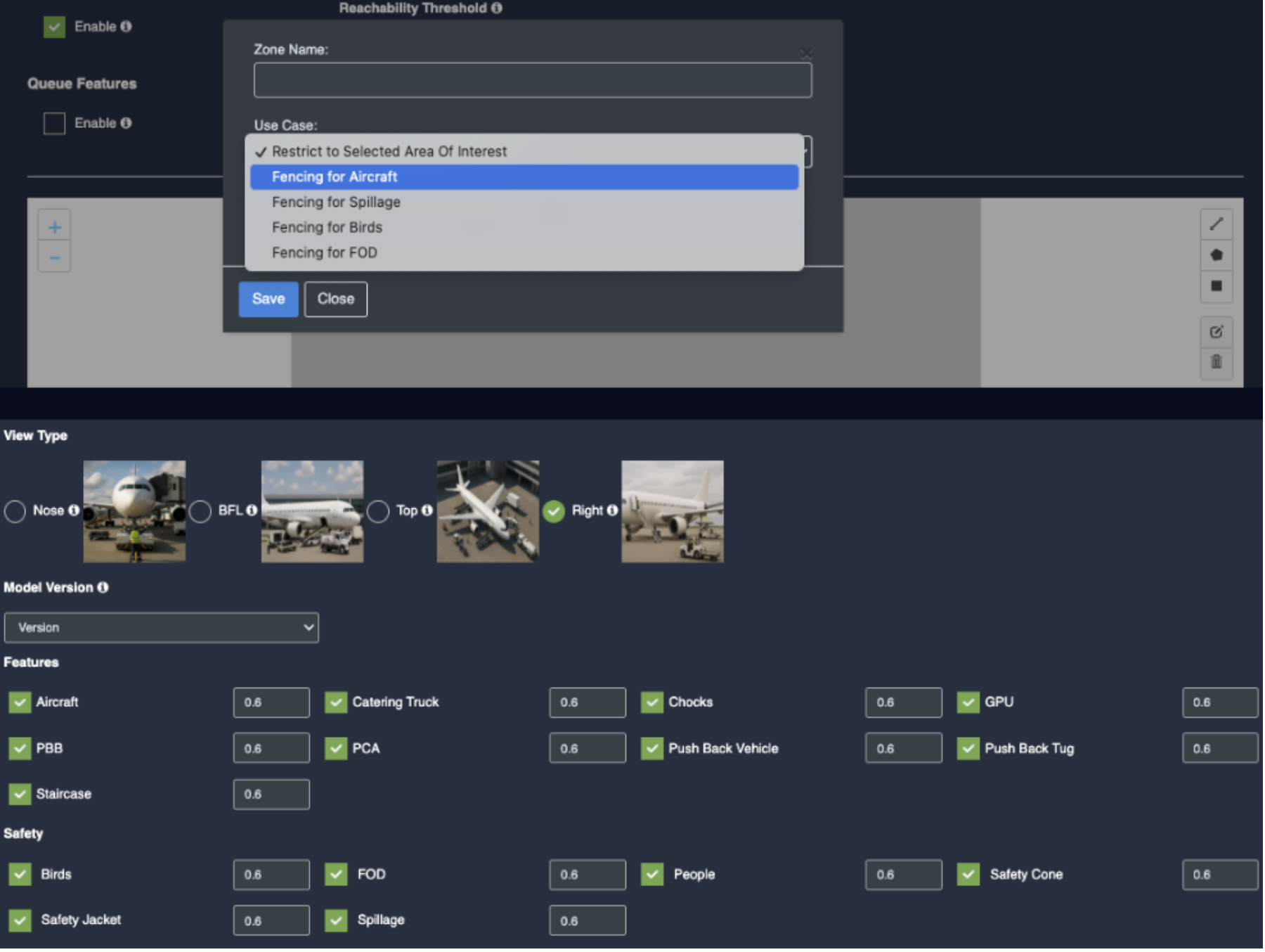
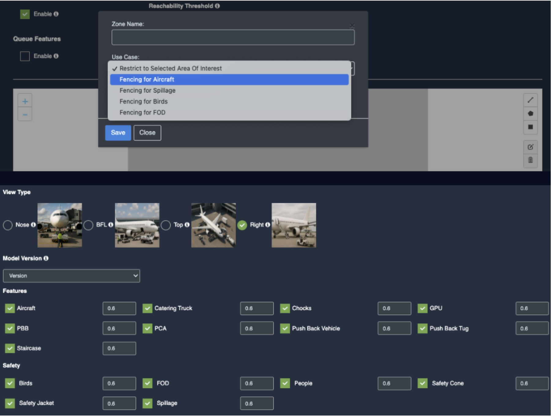
Enter the zone name in the popup window that opens and click the Save button.
New ROI zone added successfully. Face detection will only happen when people enter this zone.
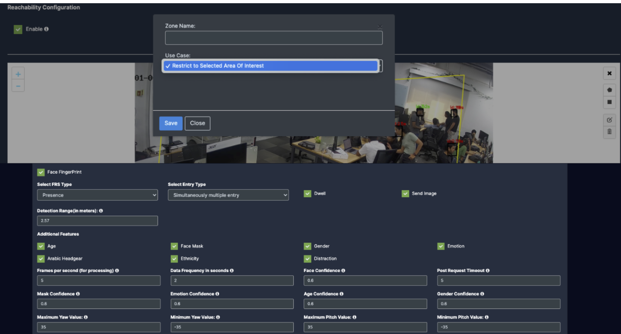
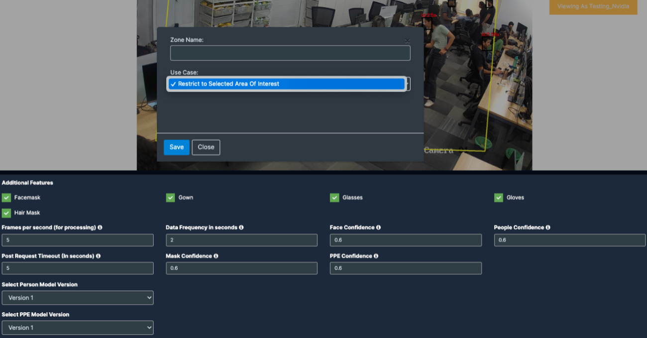
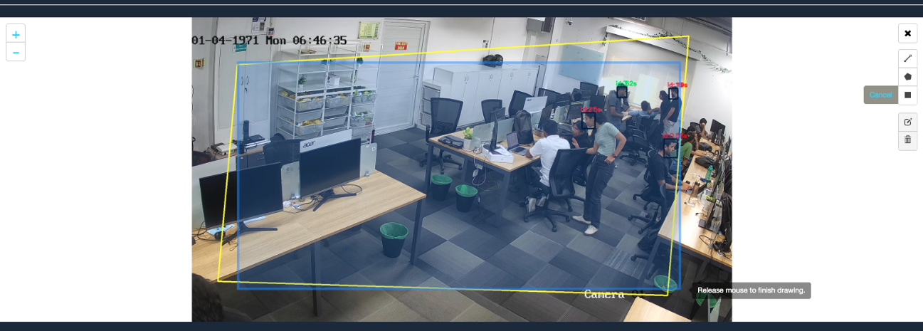
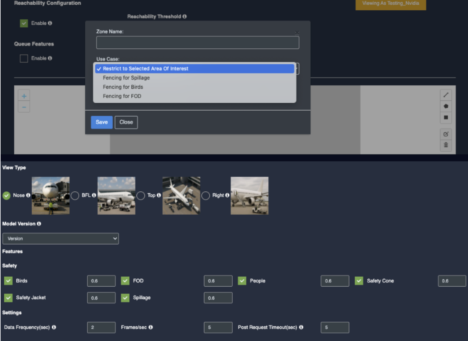
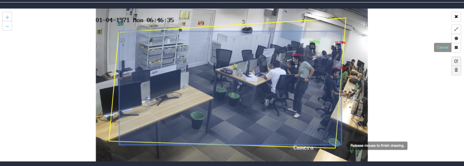
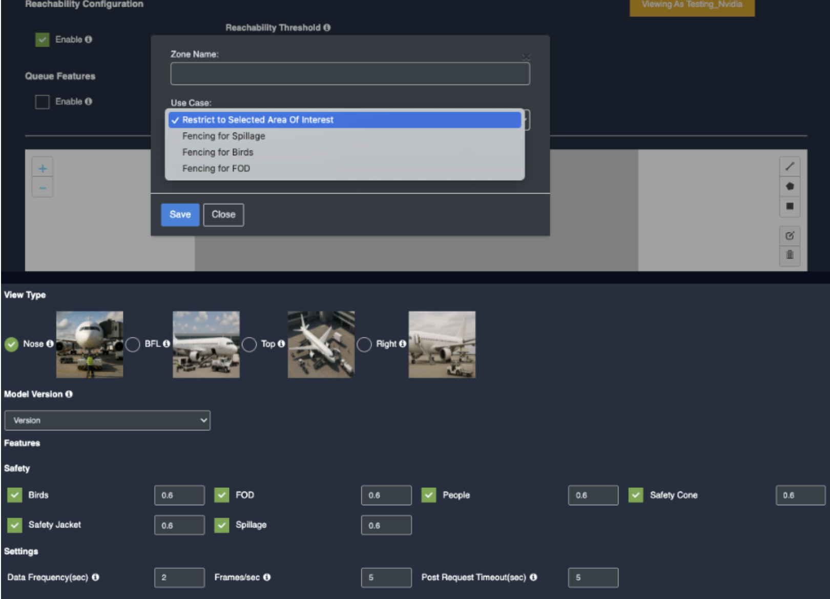
Draw ROI using the rectangle tool.
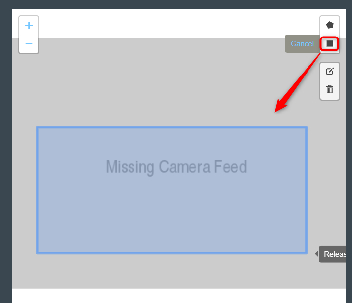
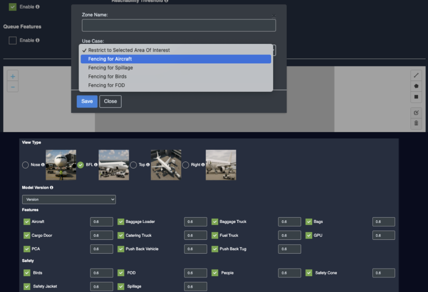
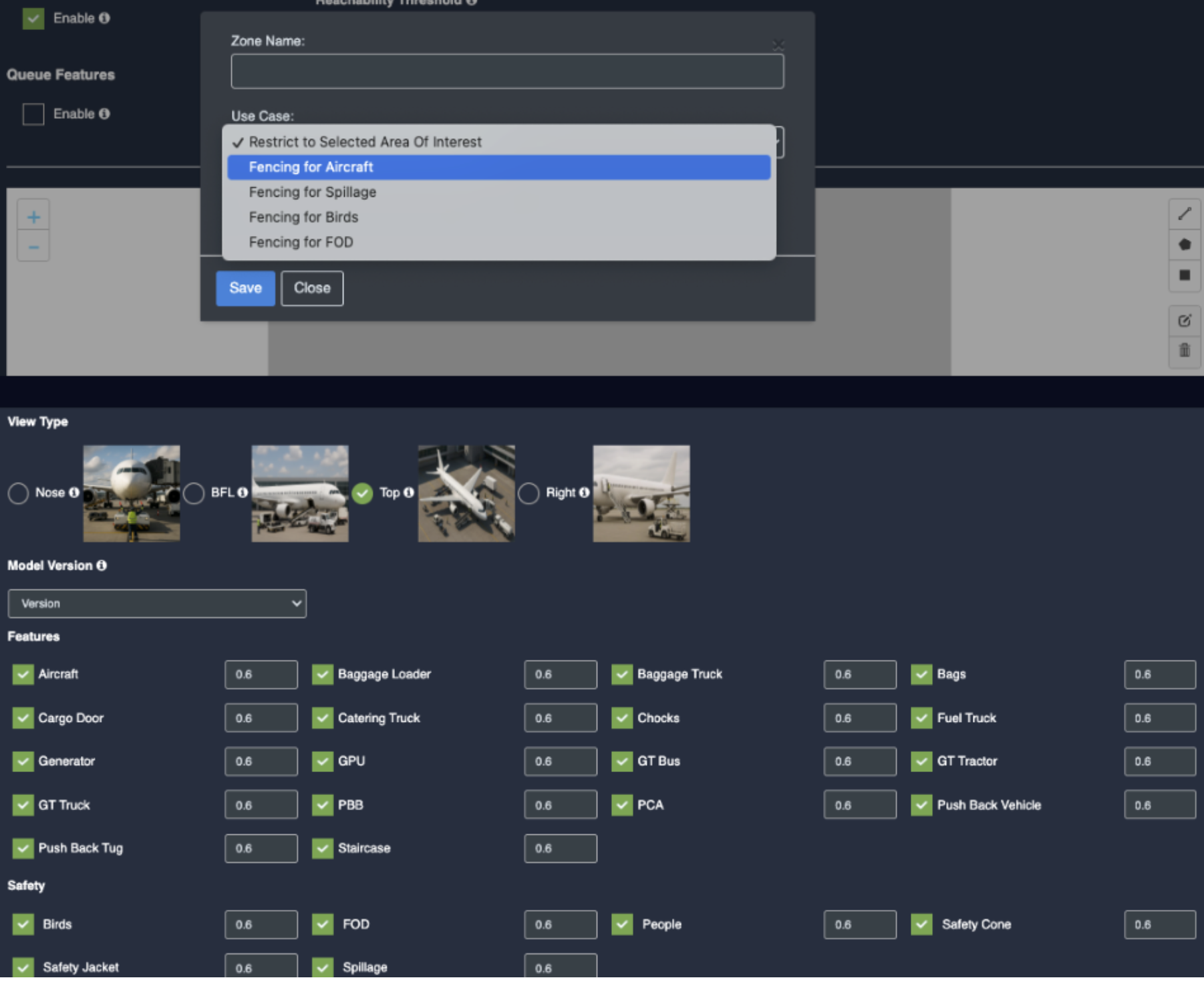
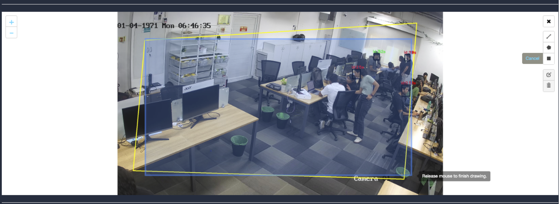
Click on the Rectangle tool button from the camera frame.
Then draw the rectangle where you want to focus the camera.
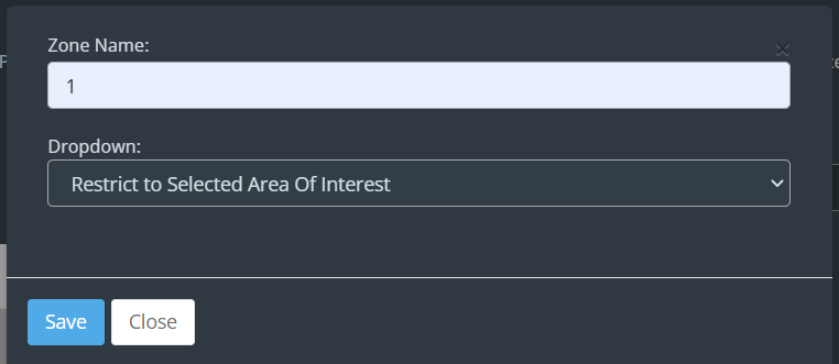
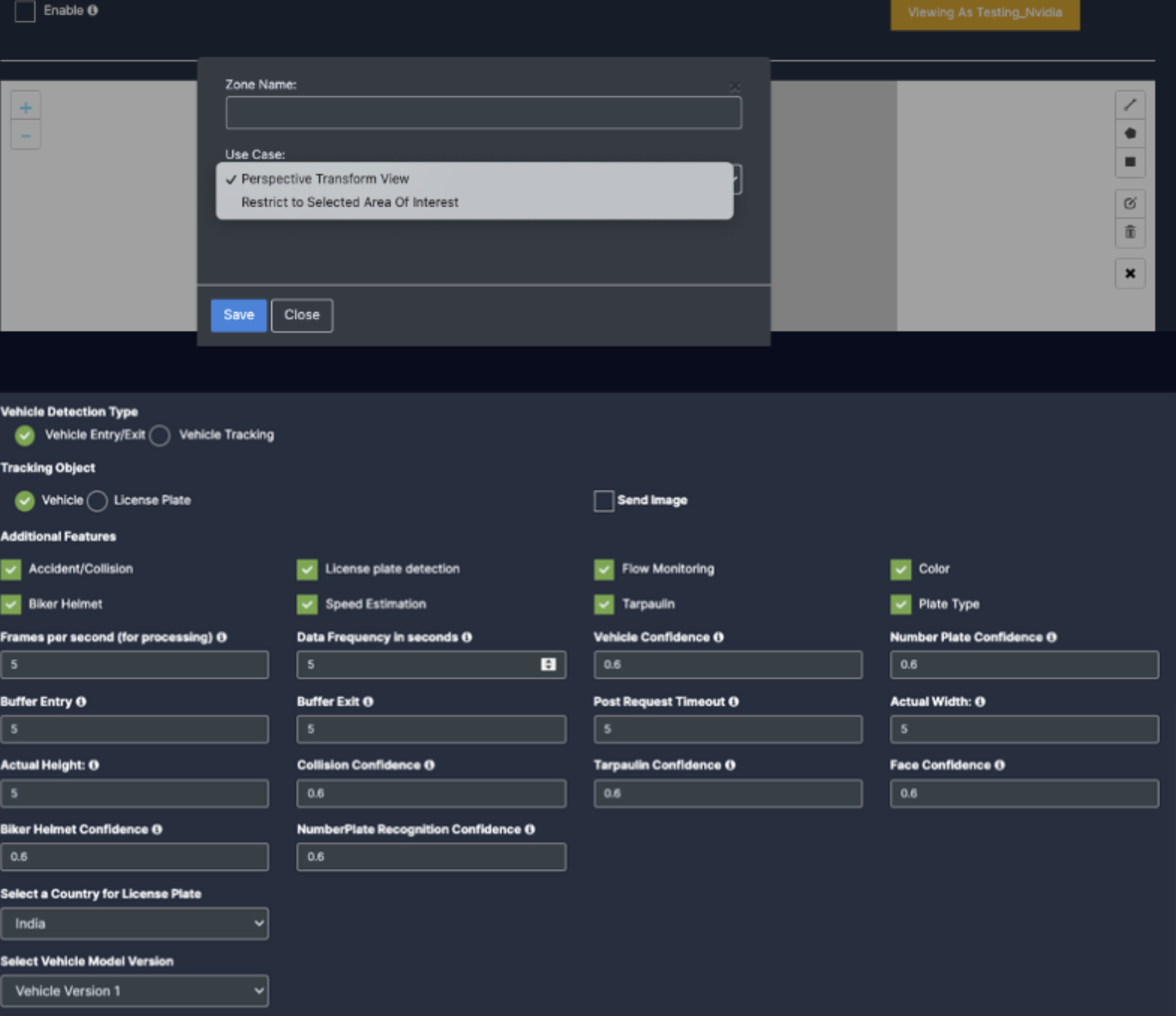
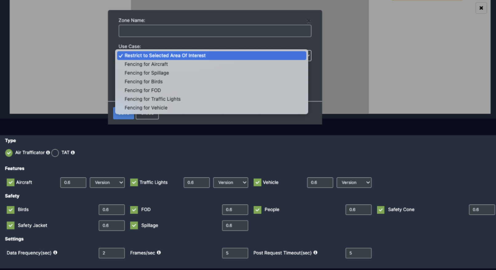
Then enter the zone name and select Restrict to selected area of interest option from the dropdown list and click the Save button.
Face detection will only happen when people enter this zone.
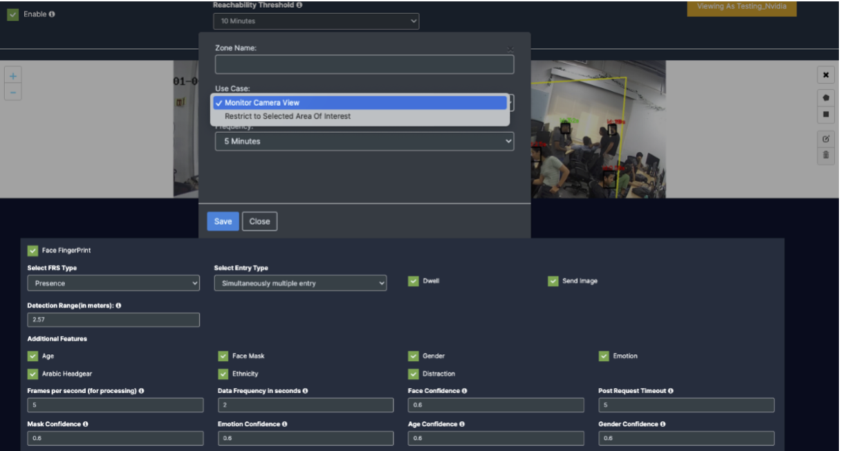
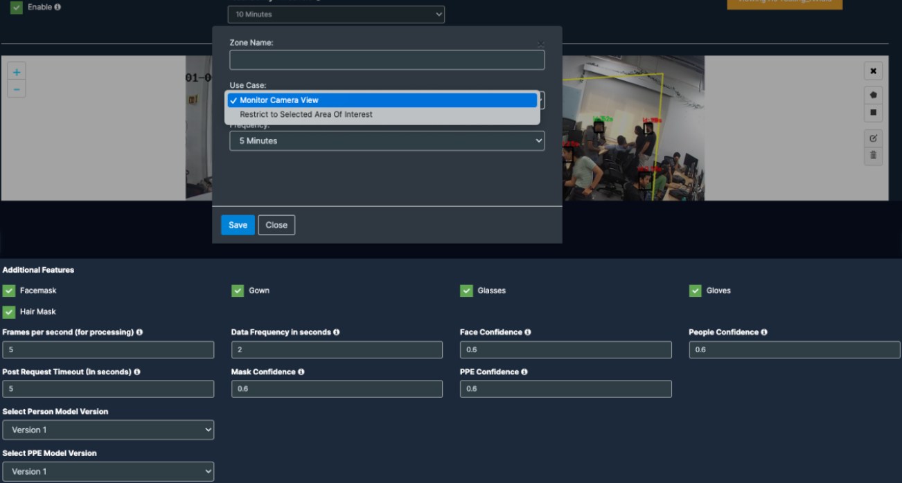
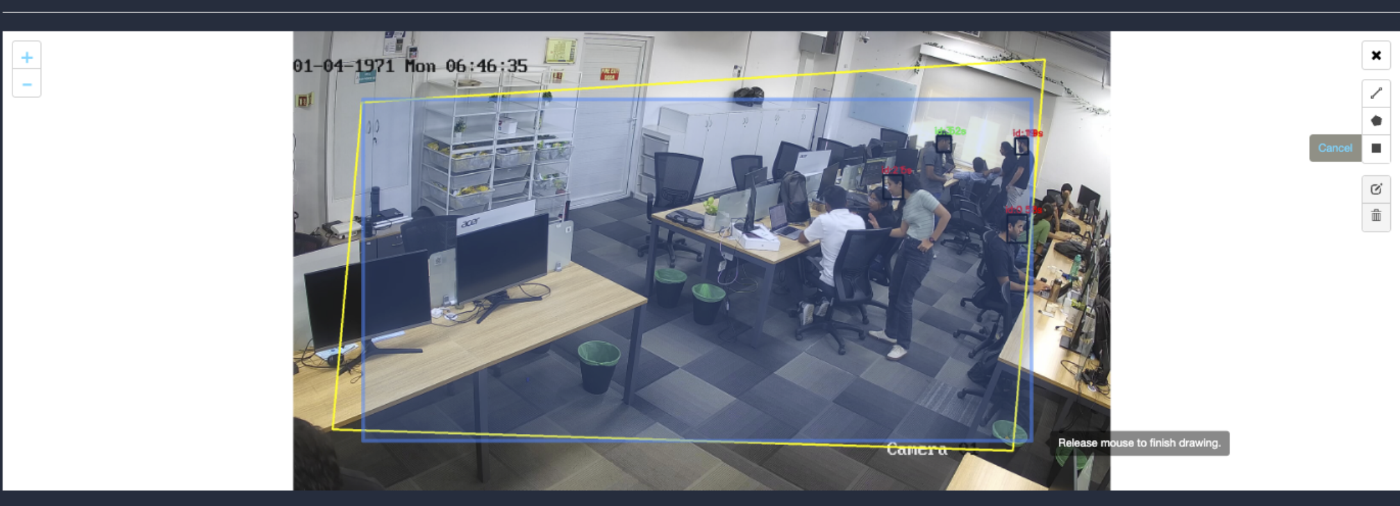
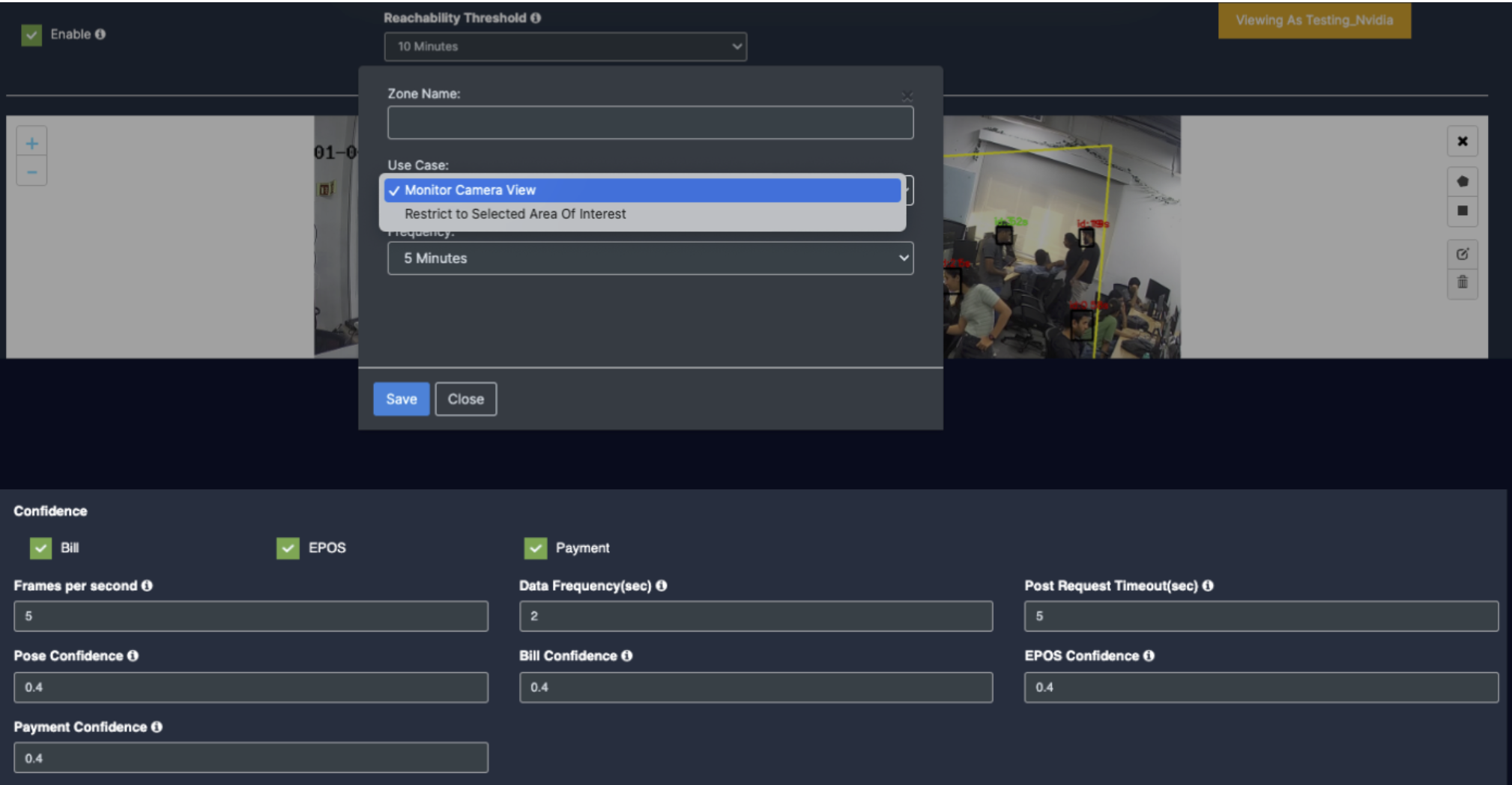
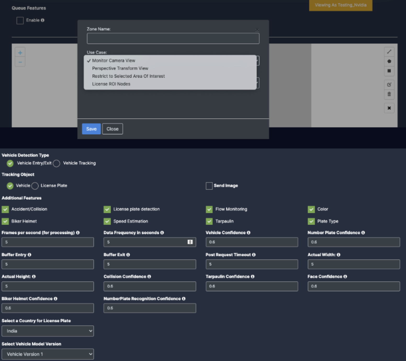
Monitor camera view.
Monitor camera view is used to detect changes in camera angle or position. An ROI needs to be determined for that.
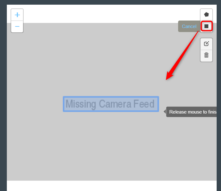
To do so, click on the Rectangle tool button from the camera frame.
Then draw the rectangle where you want to draw the ROI.
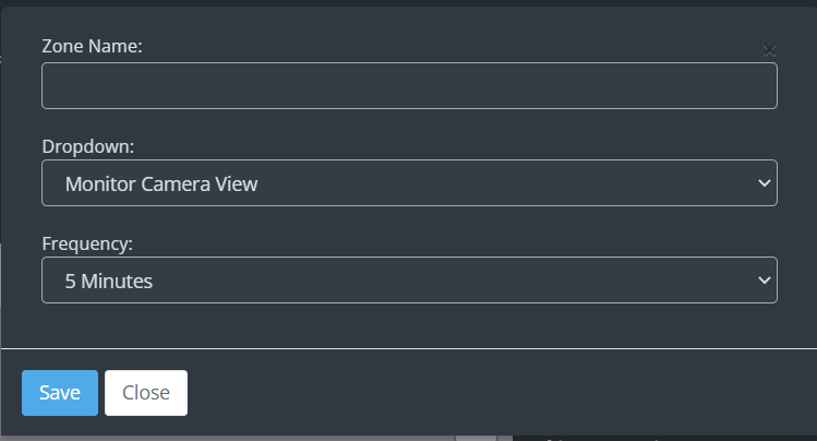
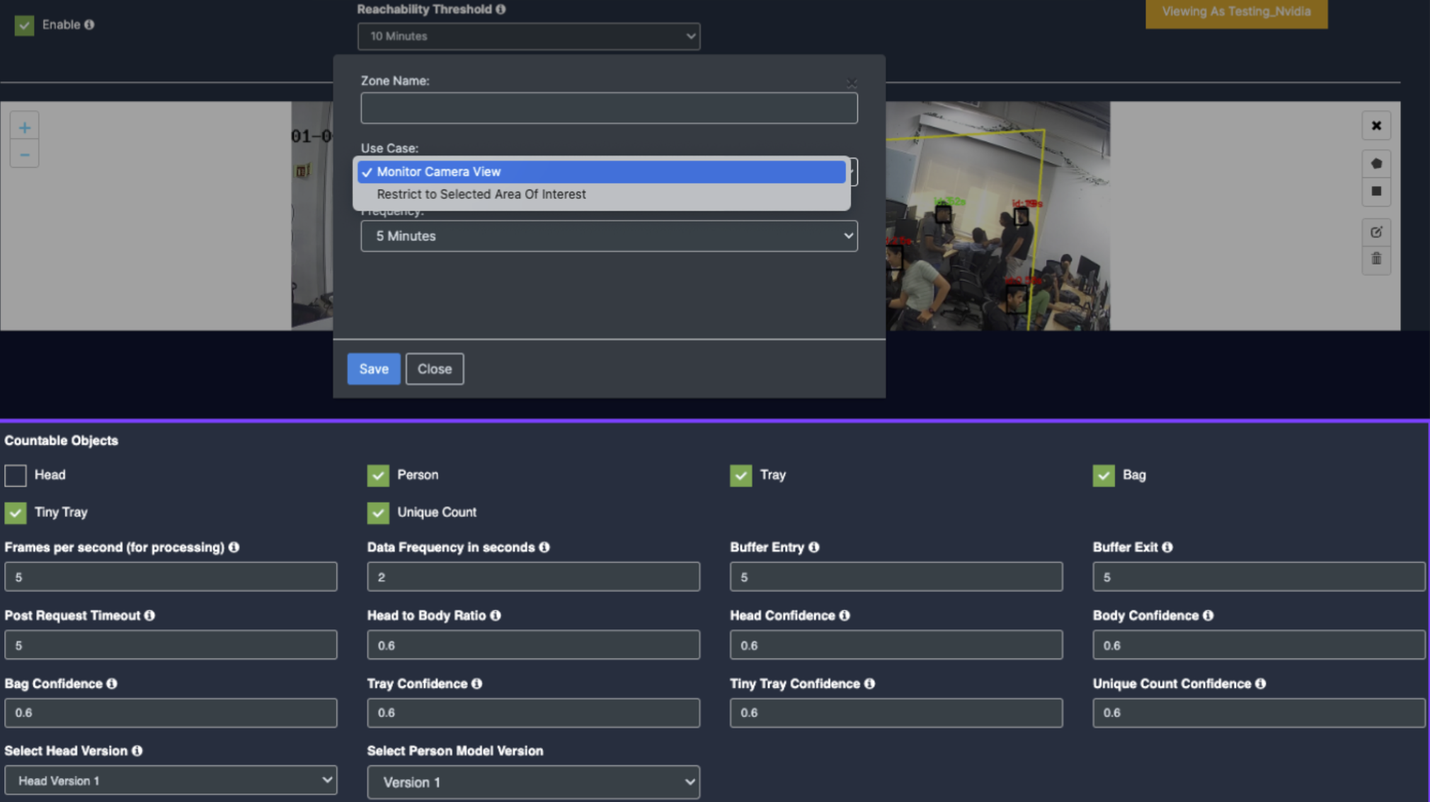
Then enter the zone name and select the Monitor Camera View option from the dropdown list.
Then, select how often you want to observe the change in focus from the Frequency dropdown list and click the Save button and click the Save button.
Now if the camera moves vertically or horizontally from the focus point, it will detect and show how far it has moved.
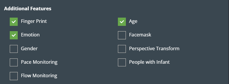
Additional features of ‘Face detection’
You can enable the features you want in the additional feature section that follows.
Age: The age of the person in front of the camera is determined and forwarded to KloudInsights for analysis.
Face fingerprint: It helps in the identification of people detected on the camera using characterisations obtained from the database.
Emotion: Understanding a person’s emotions with the help of demographics.
Facemask: Detects whether the person in front of the camera is wearing a mask or not and, if not, prompts them to wear one.
Gender: Identifying a person’s gender depending on the demographics.
Arabic Headgear: To detect if a person is wearing Arabic/Emirati Headgear.
Note: This feature only works if Kiosk mode is enabled.
Ethnicity: To detect the ethnicity of a person.
Note: This feature only works if Kiosk mode is enabled.
Perspective Transform: The coordinates of the person are transformed from a camera perspective to new coordinates based on the perspective ROI and hence used for calculating the actual distance between the person.
Pace Monitoring: It helps to assess a person’s speed.
People with Infant: It helps to identify those who are traveling with an infant.
Flow Monitoring: This helps to detect if someone is breaking the entry/exit flow.
Configuring the Face detection parameters
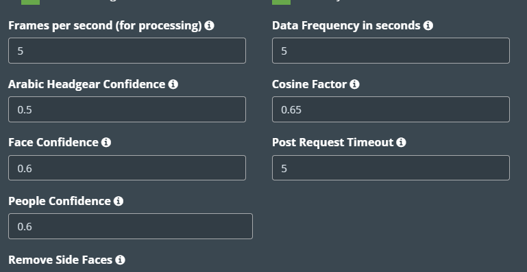
Next, you have to enter the necessary parameters for face detection to work efficiently. For that fill in the details given below.
Frames per second, Data Frequency in seconds, Face Confidence, Post Request Timeout, and People Confidence, are common in some use cases. Refer General Configuration section to know more about these.
Arabic Headgear confidence: This feature shows the probability of a person wearing an Arabic/Emirati Headgear. It only needs to be configured if the ‘Arabic Head Gear’ option is enabled. The default value of Arabic Head Gear confidence is 0.5.
Cosine factor: the Cosine factor determines the uniqueness of faces detected by the cameras. The default value of cosine factor is .65.
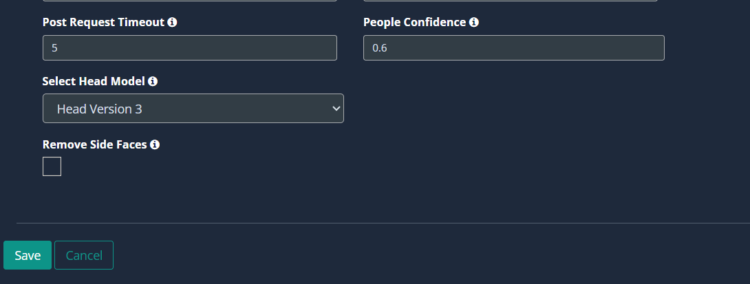
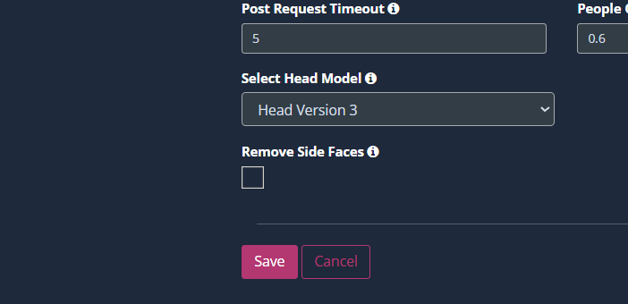
Select Head Model: The head model can be selected based on the resolution, distance, angle, and available light of the camera used.
Head version 1: Works only on good lighting with any resolution. The maximum distance of the camera can be 15 meters with an angle range of 60°-80°
Head version 2: Works only on good lighting with a resolution of 640 x 480. The maximum distance of the camera can be 70 meters with an angle range of 80°-90°
Head version 3: Works on low and good lighting with a resolution starting from 640 X 480 to 4k. The maximum distance of the camera can be 120 meters with an angle range of 60°-90°
Head version 4: Works on low and good lighting with a resolution starting from 640 X 480 to 4k. The maximum distance of the camera can be 300 meters with an angle only of 90°
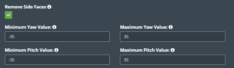
Remove side faces: Eliminates the side profile face of an individual for better accuracy in detecting demographics.
Min Yaw Value and Max Yaw Value: If this limit is set to more than -35 or +35, ignore the detection of faces in the left/right direction.
Min Pitch Value and Max Pitch Value: If this limit is set to more than -35 or +35, ignore the detection of faces in the up/down direction.
Finally, click the Save button to save the changes.
Personal protective equipment (PPE) detection Configuration
If you want to configure any of the following use cases on your camera, you can configure it using the PPE detection feature.
Construction Use Cases
Face mask detection
Hard hat Helmet
Safety vest
Healthcare Use Cases
Face mask detection
Glasses detection
Gloves detection
Gown detection
Hair mask detection
Before you begin configuring the use cases, you should first configure the camera’s general configuration. Refer to the General Camera Configuration section for instructions.
Then, follow the steps below to configure PPE detection on your chosen camera.
Select the PPE Detection from the dropdown list.
Then, select the industry you wish to configure.
Construction
Health Care
Scroll down and choose your preferred use cases. You can choose multiple use cases.
ROI in camera frames can help to improve efficiency, accuracy, and reduce storage requirements.
If ROI is not added, the model will detect the entire frame.
For PPE detection, ROI can be drawn in two ways.
Using the polygon tool.
Using the rectangle tool.
Refer to Draw ROI using the Polygon tool, Draw ROI using the rectangle tool, and Monitor camera view. Section from the Face Detection for more details.
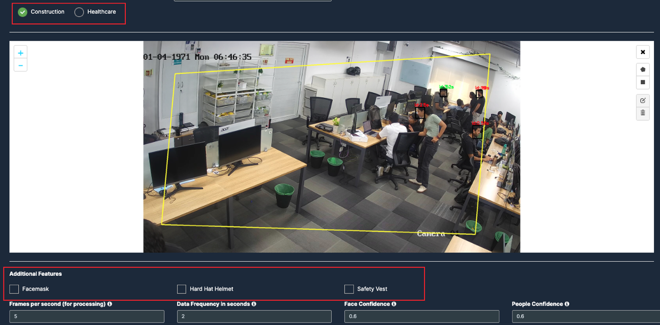
Additional Features of Construction
Facemask: KloudVision determines whether people visible to the camera are wearing face masks or not. This is useful in COVID 19 use cases where for safety it is recommended to wear masks. The number of people detected wearing a mask and
not wearing a mask are sent to KloudInsights.
Safety Vests: KloudVision determines whether people in the camera’s view are wearing safety vests. These analytics are sent to KloudInsights. This is useful in site safety scenarios for construction businesses where it is mandatory to wear these safety vests.
Hard Hat Helmet: KloudVision determines whether people in the camera’s view are wearing hard hat helmets. This is useful in site safety scenarios for construction businesses where it is mandatory to wear these hard hat helmets.
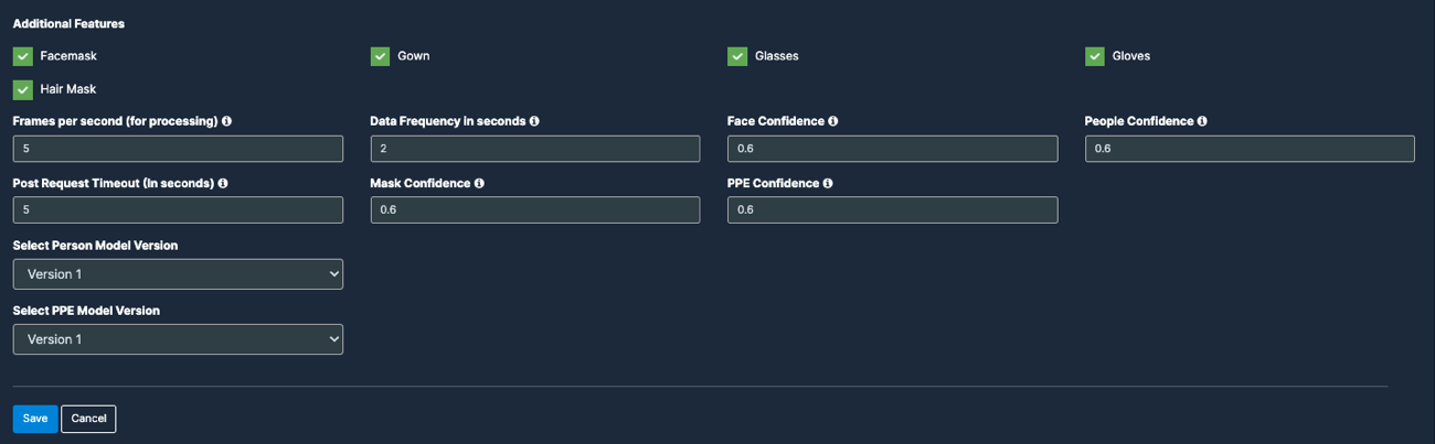
Additional Features of Healthcare
You can check the features you want in the additional feature section that follows.
Facemask: KloudVision determines whether the person detected by the camera is wearing a facemask.
Gown: This feature determines whether a person detected by the camera is wearing a medical gown.
Glasses: KloudVision determines whether a person detected by the camera is wearing safety glasses.
Hair Mask: KloudVision determines whether a person detected by the camera has a hair mask on.
Gloves: This determines whether a person detected by the camera is wearing hand gloves.
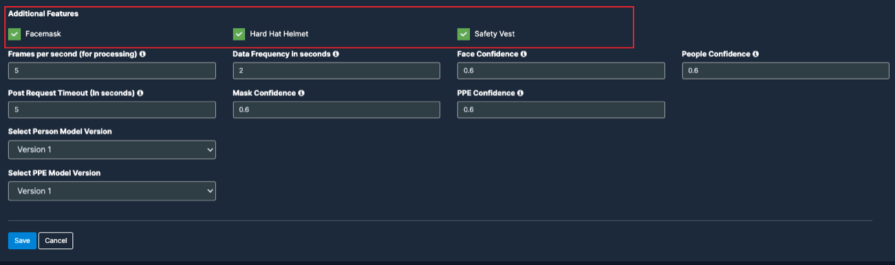
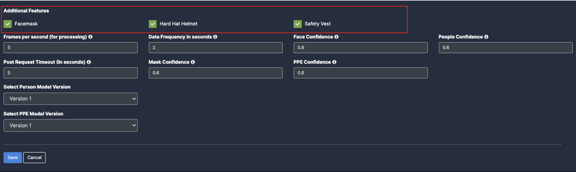
Configuring the PPE detection options
Next, you have to enter the necessary parameters for PPE detection to work efficiently. For that fill in the details given below.
Frames per second, Data Frequency in seconds, Face Confidence, Post Request Timeout, and People Confidence, are common in some use cases. Refer General Configuration section to know more about these.
Click the Save button to save the changes.
Entry/Exit Count Configuration
If you want to configure any of the following use cases on your camera, you can configure it using the Entry/Exit Count feature.
Entry/Exit Count
Fingerprint detection
Face mask detection
Gender detection
Follow the steps below to configure the ‘Entry/Exit count’ on your chosen camera.
Before you begin configuring the use cases, you should first configure the camera’s general configuration. Refer to the General Camera Configuration section for instructions.
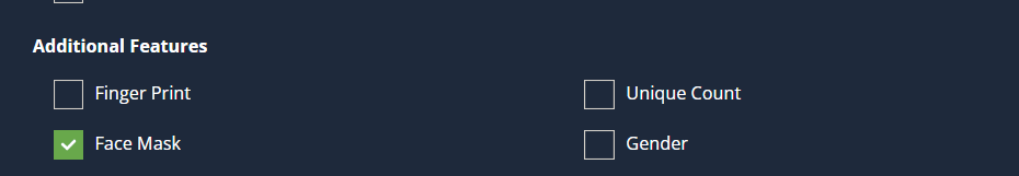
Along with the entry/exit count, you can utilize the following functionalities. Check the checkboxes for the features you want to add.
Fingerprint: It helps in the identification of people detected on the camera using characterisations obtained from the database.
Facemask: KloudVision determines whether people visible to the camera are wearing face masks or not.
Age and Gender: The age and gender of the person in front of the camera is determined and forwarded to KloudInsights for analysis.
Unique Count: It is useful to assign a unique count to the individual viewed on camera.
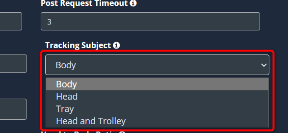
Depending on the camera’s location, you can change the subject being tracked. If the camera is positioned above the head, you can choose Tracking Subject as Head. If it is below the head level, you can choose the body.
If you want to track a Tray, select Tray. You can select Head and Trolley and count the number of trolley and humans entering or exiting.
You can edit the default parameters to get more accurate entry/exit count. Refer to the Configuring the entry and exit options section to learn what this is and how to change it.
Click the Save button to save the configuration.
Draw ROI (region of interest) on the camera frame.
ROI in camera frames can help to improve efficiency, accuracy, and reduce storage requirements.
Note: An entry/exit separator is mandatory to calculate the entry/exit count.
Two drawings are required for the entry/exit count. Here ROI is optional. If ROI is not added, the model will detect the entire frame.
drawings are required for entry/exit count. Here ROI is optional.
Entry/Exit Separator
ROI
For Entry/Exit count, ROI can be drawn in two ways.
Using the polygon tool
Using the rectangle tool.
Refer to Draw ROI using the Polygon tool., Draw ROI using the rectangle tool., and Monitor the camera view. Sections from the Configure Face Detection for more details.
Draw an Entry/Exit Separator
An entry/exit separator can be drawn using a polyline. It is mandatory for entry exit counting.
Entry or exit count is taken based on this line. Entry is determined in two ways.
Horizontally, top to bottom,
Vertically, left to right.
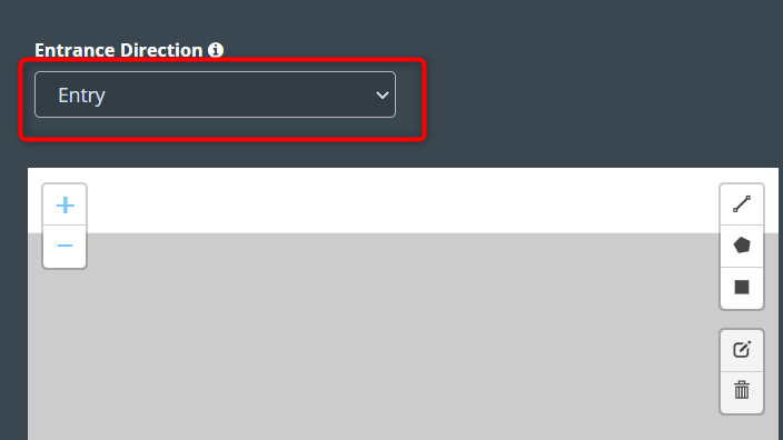
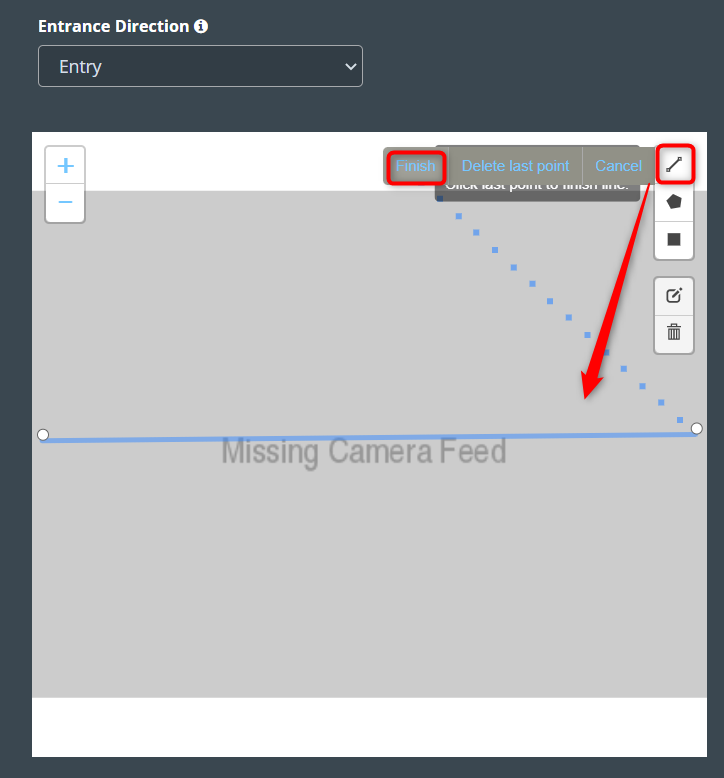
If you want to configure an entry count horizontally, follow the steps below.
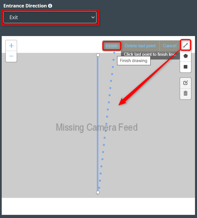
Select the Entry option from the Entrance direction dropdown list.
Then, draw a horizontal line using a polyline tool. This line should have only two points.
After drawing click the Finish button.
Then enter the zone name in the popup window that opens and click the Save button.
Note: In this scenario, an entry is recorded if an object crosses the entry/exit separator from top to bottom.
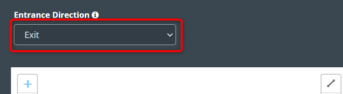
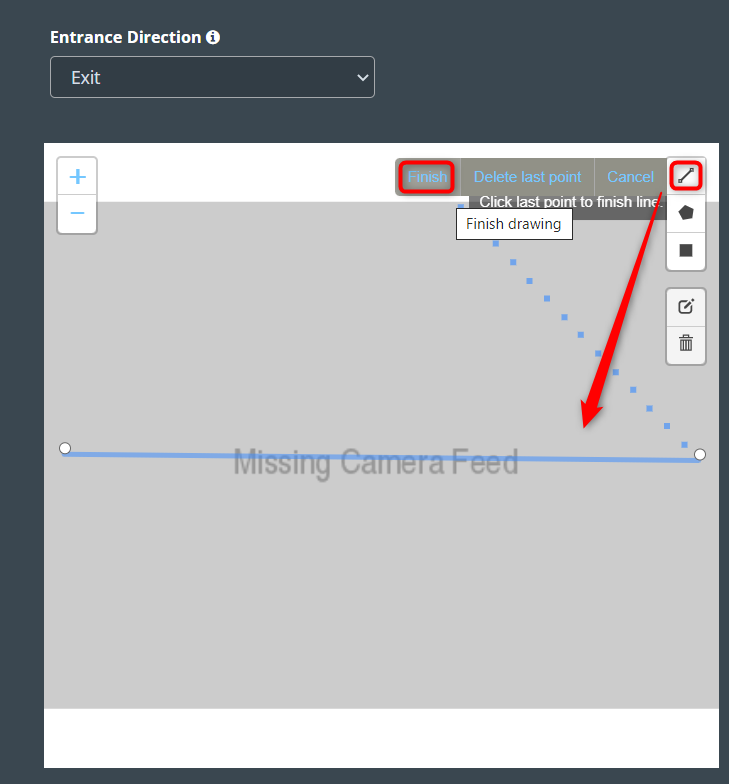
If you want to configure an Exit count horizontally, follow the steps below.
Select the Exit option from the Entrance direction dropdown list.
Then, draw a horizontal line using a polyline tool. This line should have only two points.
After drawing click the Finish button.
Then enter the zone name in the popup window that opens and click the Save button.
Note: In this scenario, an Exit is recorded if an object crosses the entry/exit separator from top to bottom.
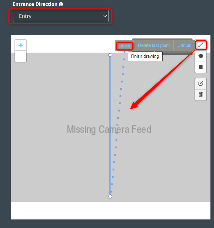
If you want to configure an entry count vertically, follow the steps below.
Select the Entry option from the Entrance direction dropdown list.
Then, draw a vertical line using a polyline tool. This line should have only two points.
After drawing click the Finish button.
Then enter the zone name in the popup window that opens and click the Save button.
Note: In this scenario, an entry is recorded if an object crosses the entry/exit separator from left to right.
If you want to configure an Exit count vertically, follow the steps below.
Select the Exit option from the Entrance direction dropdown list.
Then, draw a horizontal line using a polyline tool. This line should have only two points.
After drawing click the Finish button.
Then enter the zone name in the popup window that opens and click the Save button.
Note: In this scenario, an Exit is recorded if an object crosses the entry/exit separator from left to right.
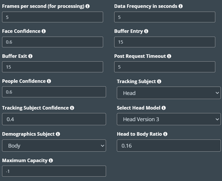
Configuring the entry and exit options:
Buffer entry: This is an upside Pixel distance from middle line.
Buffer Exit: This is a downside Pixel distance from the middle line.
Tracking Subject: When tracking the camera, it decides whether to track the body or the head. When body tracking is occluded in crowded areas, head tracking can be used.
Boady: Entry/exit count is taken by full body tracking.
Head: Entry/exit count is taken by head tracking.
Tray: Counting the number of trays using the tracking tray. It can be used in places like Airports.
Tracking Subject Confidence: This value is the probability for the tracking subject chosen.
Select Head Model: The head model can be selected based on the resolution, distance, angle and available light of the camera used.
Head version 1: Works only on good lighting with any resolution. The maximum distance of the camera can be 15 meters with an angle range of 60°-80°
Head version 2: Works only on good lighting with a resolution of 640 x 480. The maximum distance of the camera can be 70 meters with an angle range of 80°-90°
Head version 3: Works on low and good lighting with a resolution starting from 640 X 480 to 4k. The maximum distance of the camera can be 120 meters with an angle range of 60°-90°
Head version 4: Works on low and good lighting with a resolution starting from 640 X 480 to 4k. The maximum distance of the camera can be 300 meters with an angle only of 90°
Demographics Subject: Helps to calculate the gender and age of the person entering, using their body and face.
Head to Body Ratio: This value can be used to determine whether the person entering is an adult or a child. If the ratio is greater than 0.16, the person is considered an adult; if it is less than 0.16, the person is considered a child.
Maximum Capacity: It helps determine the maximum number of people a zone can accommodate.
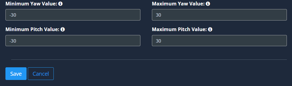
Remove side faces: Eliminates the side profile face of an individual for better accuracy in detecting demographics.
Min Yaw Value and Max Yaw Value: If this limit is set to more than -35 or +35, ignore the detection of faces in the left/right direction.
Min Pitch Value and Max Pitch Value: If this limit is set to more than -35 or +35, ignore the detection of faces in the up/down direction.
Frames per second, Data Frequency in seconds, Face Confidence, Post Request Timeout, and People Confidence, are common in some use cases. Refer General Configuration section to know more about these.
Click the Save button to save the changes.
Social Distancing Configuration
Social distancing monitoring with KloudVison helps track the movements and distances of individuals and ensure they follow recommended social distancing guidelines.
Follow the steps below to configure ‘Social Distance’ on your chosen camera.
Select the Social Distance Option from the dropdown list.
Before you begin configuring the use cases, you should first configure the camera’s general configuration. Refer to the General Camera Configuration section for instructions.
Draw ROI (region of interest) on the camera frame.
ROI in camera frames can help to improve efficiency, accuracy, and reduce storage requirements.
Two drawings are required to track social distancing.
Vertical and horizontal distance
Social distance ROI nodes
Follow the steps given below to draw Vertical and horizontal distance.
Draw a horizontal line using a polyline tool. It will have three points.
After drawing, click the Finish button.
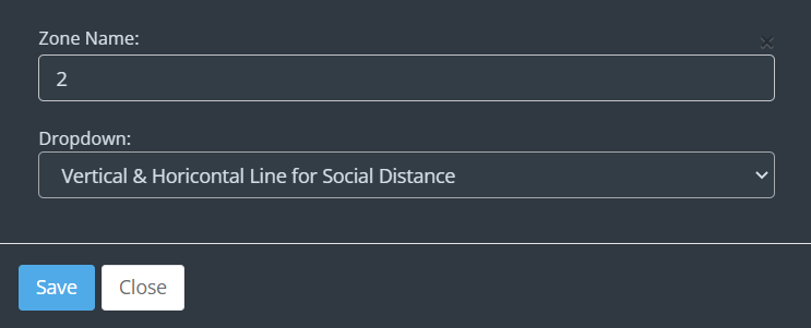
Then enter the zone name in the popup window that opens and click the Save button.
Vertical and horizontal distance lines were added successfully.
Follow the steps given below to draw social distance ROI nodes.
Note: Social distance ROI should be drawn only using the polygon tool.
Refer to Draw ROI using the Polygon tool Section from the Configure face
detection for more details.
Note : Polygon ROI should have only 4 points.
Configuring the social distancing Parameters
Frames per second, Data Frequency in seconds, Post Request Timeout, and People Confidence , are common in some use cases. Refer General Configuration section to know more about these.
Click the Save button to save the changes.
Vehicle Detection Configuration
The Vehicle Detection option can be used to configure use cases related to vehicles. Currently, three types of vehicle detection are available.
Vehicle entry/exit count: Vehicle Entry/Exit Counting with Kloudvision helps in detecting and tracking
vehicles entering and exiting a particular location to provide accurate
figures and data for traffic analysis and management purposes.
Vehicle tracking: It helps in vehicle tracking by utilizing various vehicle characteristics.
Vehicle parking lots: Vehicle parking lot monitoring using KloudVision helps monitor the
occupancy of parking lots and detect parking violations.
Follow the steps below to configure ‘Vehicle Detection’ on your chosen
camera.
Select the Vehicle Detection from the dropdown list.
The sensor features are the next thing to configure. It includes the
following options: Profile, Reachability, and Enable Kloudinsights. Refer
to the General Configuration section to know more about this.
Then select detection type and configure other settings.
If you want to configure the following use scenarios, as well as the number of vehicle entries and exits, Select Vehicle entry/exit count type. For instructions on how to configure this, refer to the Setup Vehicle Entry/Exit Configuration section.
License plate detection
Color detection
Biker Helmet detection
Tarpaulin detection
If you want to configure only the following use scenarios. Select Vehicle tracking type. For instructions on how to configure this, refer to the Set-up Vehicle tracking Configuration section.
Car Fingerprint detection
License plate detection
Color detection
Biker Helmet
Tarpaulin
Dirt on Vehicle
Smoke / Fire
Smoking
Door Wide Open
Boot / Bonnet Open
No of People
Safety Equipment
Pace Monitoring
Flow Monitoring
If you want to configure the following use scenarios, as well as to find the parking lot availability, Select Vehicle Parking Lot type. For instructions on how to configure this, refer to the Set up Vehicle Parking Lot Configuration section.
License plate detection
Color detection
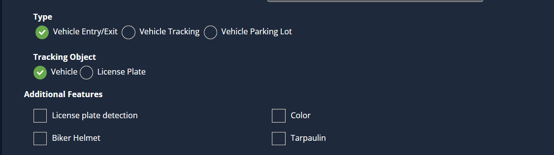
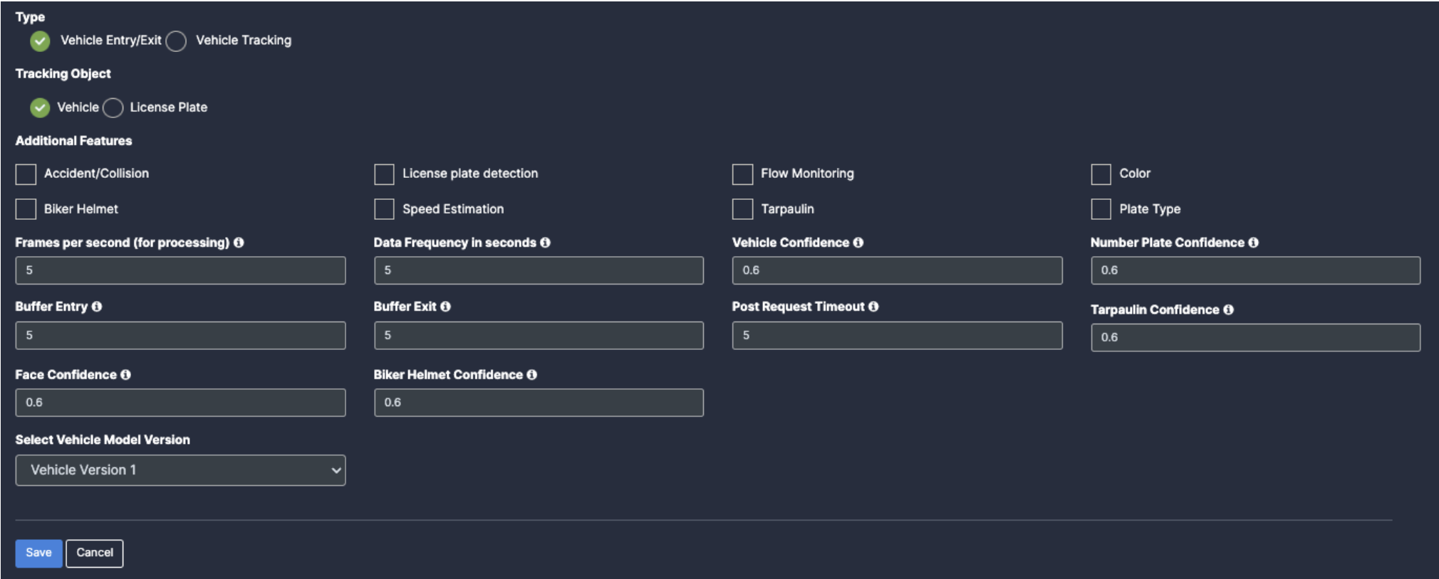
Setup vehicle Entry/Exit Configuration
Select the Vehicle Detection from the dropdown list.
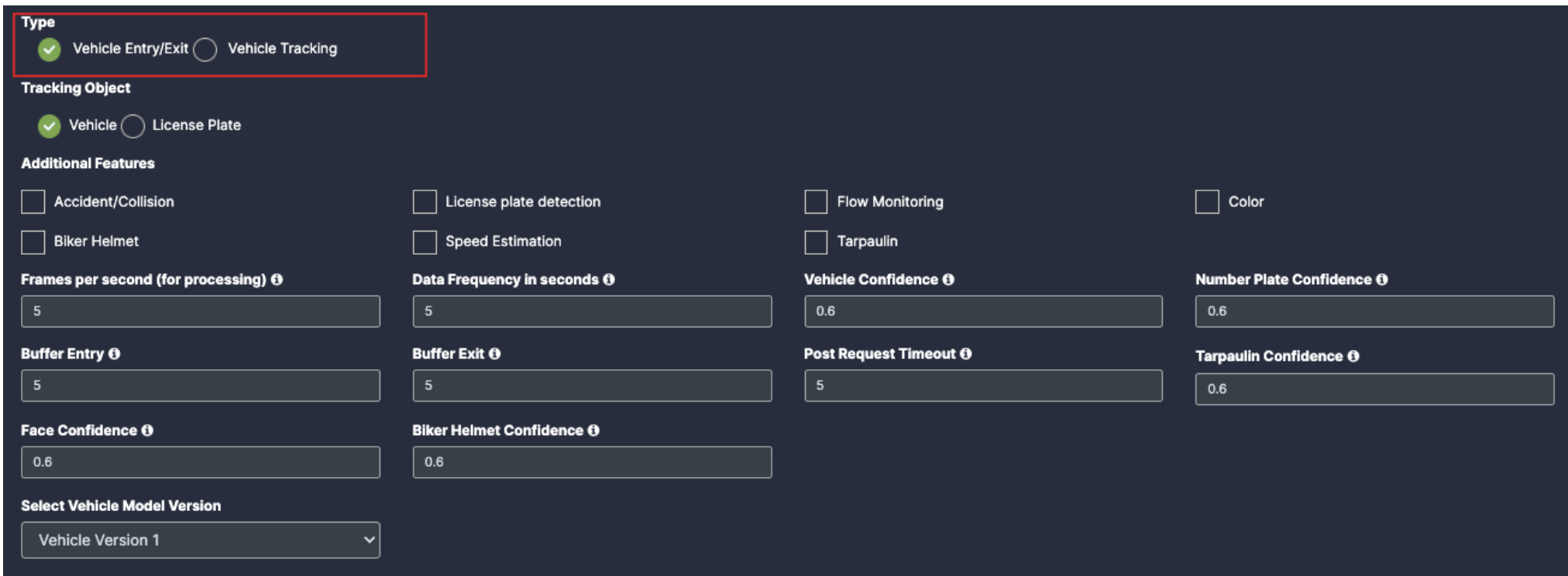
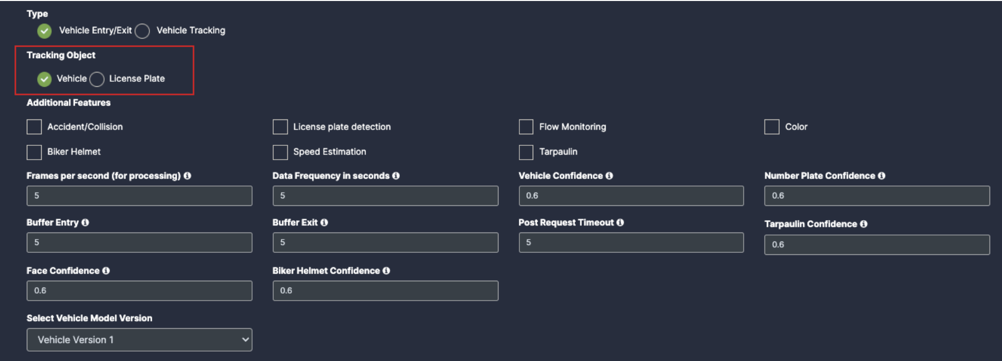
Select Vehicle Entry/Exit from the Type. Then, select the object. There are currently 2 types of objects available. Vehicle, and license plate.
Vehicle: The entry/exit of cars and trucks can be counted. License plate
detection, color detection, and Mud on tire detection are also possible.
License Plate: It helps to count entry/exit by tracking the license
plate.
If you have selected Vehicle in the tracking object, the features
given below can be enabled.
License Plate Detection: Helps in detecting the license plate of the vehicle.
Mud on tyre: This feature helps detect mud on the vehicle tires which is a safety measure to prevent hazardous driving.
Color: the camera will detect the color of the vehicle.
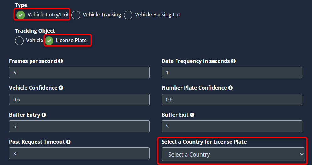
If you have selected Licence Plate in the tracking object, you can
calculate the entry and exit count by tracking the license plates. If the
license plate appears in the camera’s ROI, it is considered an entry/exit.
Some use cases require additional values; there will be a default value. If you wish to change it, you can. Refer to the Configuring the vehicle detection options section to learn what this is and how to change it.
Finally, click the Save button to save the configuration.
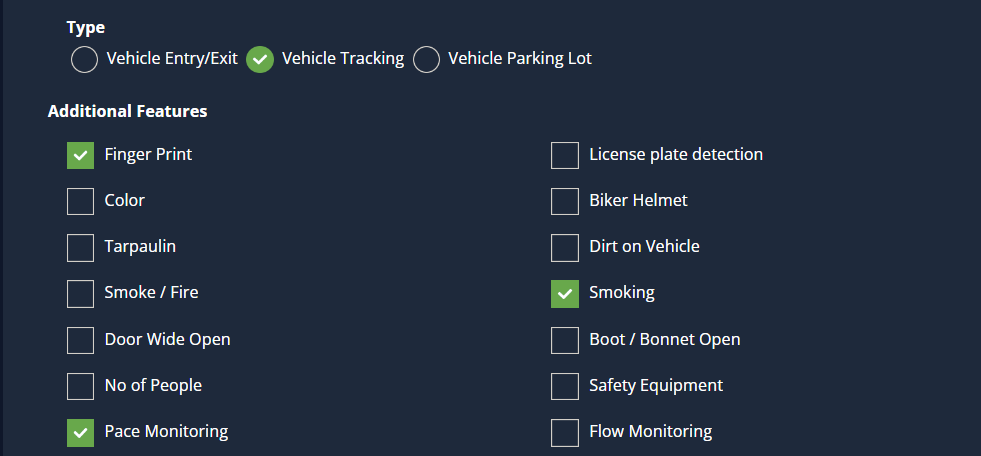
Set up Vehicle tracking Configuration.
Select the Vehicle Detection from the dropdown list.
Select Vehicle Tracking from the type. Then select the additional features you want.
Additional features of vehicle tracking
You can enable the features you want in the additional feature section that follows.
License Plate Detection : Helps in detecting the license plate of the vehicle.
Colour : Information about the colour of the vehicle.
Mud on tyre : This feature helps detect mud on the vehicle tires, which is a safety measure to prevent hazardous driving.
Dirty Vehicle : With this feature, the camera will identify whether the vehicle is clean or not.
Door Wide Open : This feature helps you find the vehicle with the door fully open.
Smoke/Fire : Used to detect the presence of smoke or fire.
Boot/Bonnet Open : This feature is used to detect bonnet/boot open vehicles.
Safety Equipment : This feature allows you to detect the absence of safety equipment in the observed area.
Smoking : This feature helps to detect smoking in the observation area.
Person coordinates : Helps to get the exact location coordinates of a person seen in the camera frame.
Pace Monitoring : Helps in the detection of vehicles traveling at less than normal speed.
Flow Monitoring : It Helps to identify vehicles violating entry/exit flow.
After selecting your desired configuration, the next step is to draw the ROI (region of interest) in the camera feed. To learn how to do this, see the steps under Draw ROI (region of interest) on camera frame.
Some use cases require additional values; there will be a default value. If you wish to change it, you can. Refer to the Configuring the vehicle detection options section to learn what this is and how to change it.
Finally, click the Save button to save the configuration.
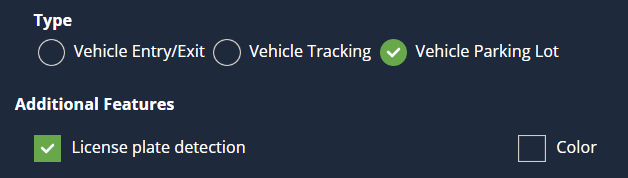
Set up Vehicle Parking Lot Configuration
This feature helps to know available parking lots in a parking area and detect parking violations. It also helps to identify the license plate and color of the parked vehicle.
Select the Vehicle Parking Lot from the type to enable this feature and select the additional features if you want.
After selecting your desired configuration, the next step is to draw the ROI (region of interest) in the camera feed. To learn how to do this, see the steps under Draw ROI (region of interest) on camera frame.
Some use cases require additional values; there will be a default value. If you wish to change it, you can. Refer to the Configuring the vehicle detection options section to learn what this is and how to change it.
Finally, click the Save button to save the configuration.
Additional features of vehicle tracking
You can enable the features you want in the additional feature section that follows.
License Plate Detection: Helps in detecting the license plate of the vehicle.
Color: Information about the color of the vehicle.
Draw ROI (region of interest) on camera frame.
ROI in camera frames can help to improve efficiency, accuracy, and reduce storage requirements.
Three drawings are required for vehicle detection.
License ROI nodes
ROI
Entry/Exit separator
Note: License ROI nodes are mandatory if license plate tracking is
enabled. ROI is optional, If ROI is not added, the model will detect the
entire frame. Entry/Exit separator is mandatory if vehicle entry/exit count is
enabled.
3. Follow the steps given below to draw License ROI nodes.
License ROI nodes are used to detect the license plates of vehicles within that ROI. This must be added while enabling license plate detection.
It is drawn using the Rectangle tool. It must be drawn within a restricted ROI.
To draw a License ROI node. Click on the Rectangle tool button from the camera frame.
Then draw the rectangle where you want to draw the ROI. This should be an area where the license plate of the vehicle can be passed.
Then enter the zone name and select the License ROI Nodes option from the dropdown list and click the Save button.
License ROI Nodes Added successfully.
4. Follow the steps given below to draw ROI. It can be drawn in two ways.
Using the polygon tool
Using the rectangle tool.
5. Refer to Draw ROI using the Polygon tool., Draw ROI using the rectangle
tool., and Monitor the camera view, Sections from Face
Detection for more details.
6. Refer to the ‘Draw an Entry/Exit Separator’ section from the Entry/Exit Count to learn how to add an entry/exit separator.
Configuring the vehicle detection options:
Vehicle Confidence: Threshold for detecting the vehicle.
Number Plate Confidence: Threshold for detecting the number plate on the vehicle.
Select country for license plate: Select which country license plate you want to detect. Currently, license plates of 3 countries can be monitored. India, Saudi Arabia, and Bahrain
Buffer entry and Buffer Exit: This is a threshold. Anyone passing through either of these boundaries and then crossing the configured middle line is said to have entered or exited as per configuration.
Frames per second, Data Frequency in seconds, and Post Request Timeout , are common in some use cases. Refer General Configuration section to know more about these.
Click the Save button to save the changes.
Video Surveillance Configuration
Video surveillance enables you to monitor an event on-site (where the camera is installed) from any location. In addition to kloudVision’s core features, Surveillance comes to you with other security benefits such as,
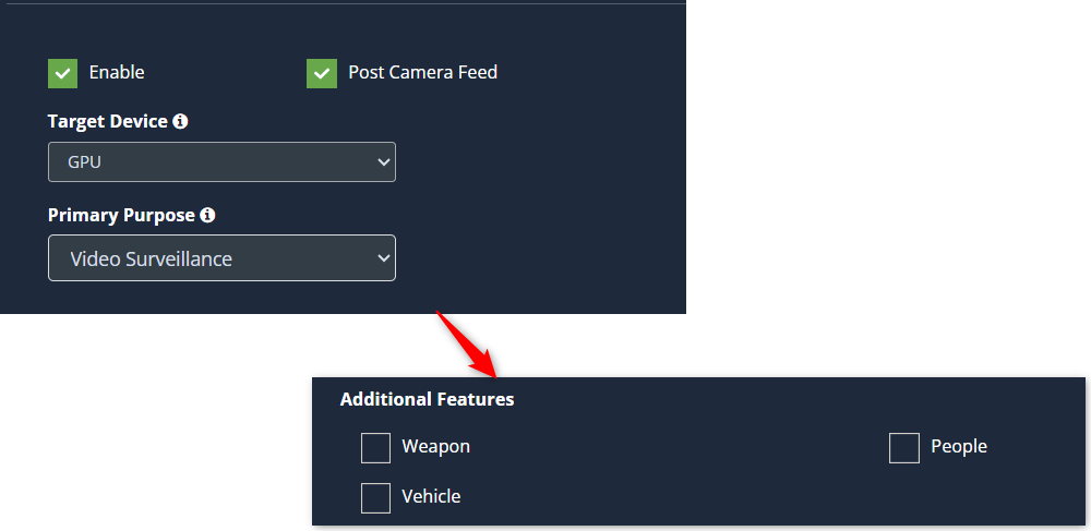
Weapon detection: If someone walks into a camera location with a weapon, the camera detects it and starts recording the event.
People detection: If someone passes in front of a camera with camera surveillance activated. The person’s age, gender, and the color of the dress are identified. It records from the time the person comes in front of the camera to the time they disappear from the camera.
Vehicle detection: When a vehicle enters the camera surveillance, it detects the type of vehicle, its color, and its license plate number. The footage will be recorded during this event.
Helmet detection : If a biker appears in front of the camera without a helmet, the camera will recognize him or her and record the incident.
Its most notable feature is that it only records when the configured event
occurs. So, finding video footage is very easy.
Follow the steps below to configure ‘Video surveillance’ on your
chosen camera.
Before you begin configuring the Video surveillance, you should first configure the camera’s general configuration. Refer to the General Camera Configuration section for instructions.
Then, select the Video surveillance from the dropdown list and select Additional Features.
Some use cases require additional values; there will be a default value. If you wish to change it, you can. Refer to the Configuring the video surveillance options section to learn what this is and how to change it.
Click the Save button to save the configuration.
Draw ROI (region of interest) on the camera frame.
ROI in camera frames can help to improve efficiency, accuracy, and reduce storage requirements.
ROI is optional. If ROI is not added, the model will detect the entire frame.
For Video Surveillance, ROI can be drawn in two ways.
Using the polygon tool
Using the rectangle tool.
Refer to Draw ROI using the Polygon tool., Draw ROI using the rectangle
tool., and Monitor the camera view. Section from the Face
Detection for more details.
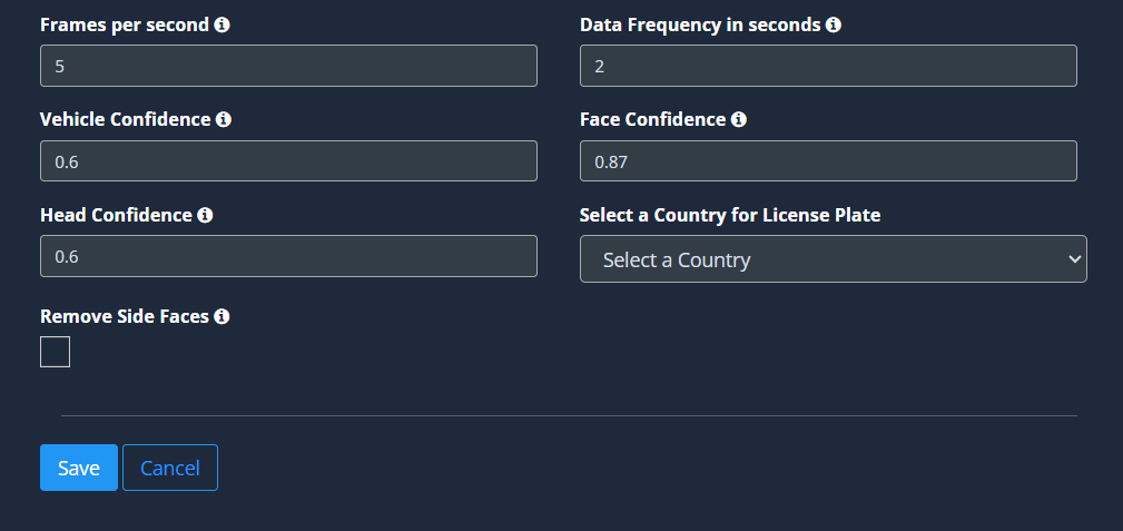
Configuring the video surveillance options:
Frames per second, Data Frequency in seconds, and Face Confidence , are common in some use cases. Refer General Configuration for various use cases section to know more about these.
Head confidence: This value is the probability that a detected shape on camera is a head. Higher values may fail to detect faces. Lower values may detect objects that are shaped like faces.
Select a Country for License Plate: Select which country license plate you want to detect. Currently, license plates of 3 countries can be monitored. India, Saudi Arabia, and Bahrain.
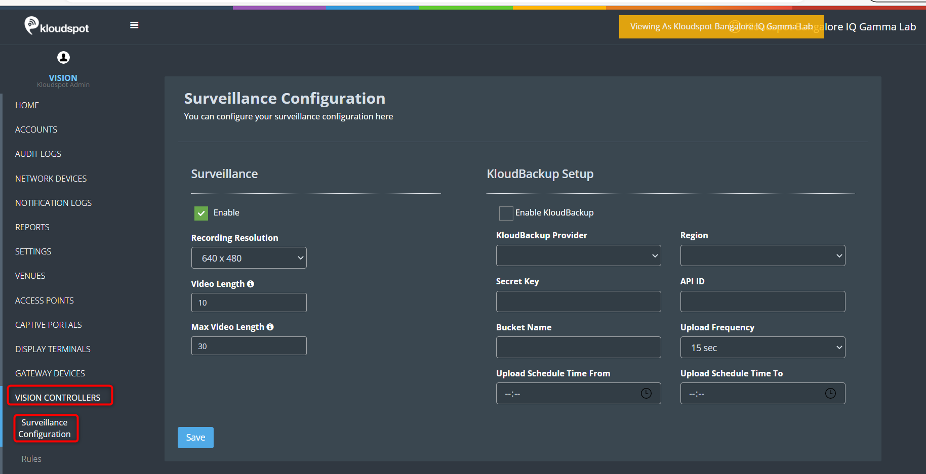
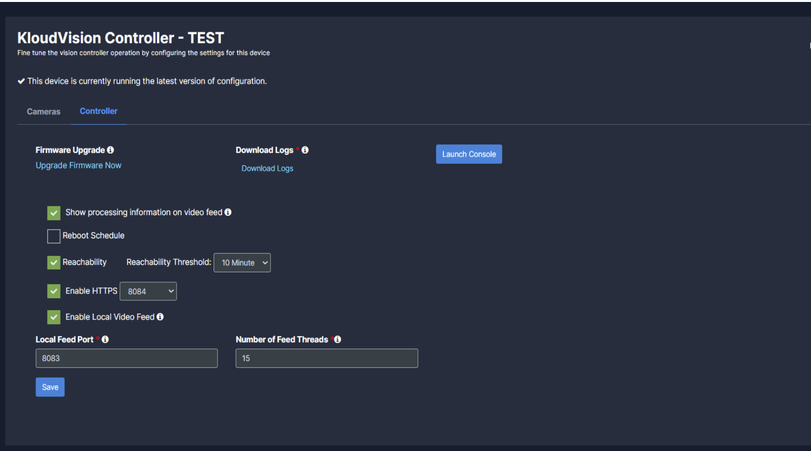
Surveillance is automatically enabled when surveillance is configured on the camera.
Navigate to VISION CONTROLLERS > Surveillance Configuration.
Uncheck the Enable check box and click the Save button to disable Surveillance.
Also, if you want to change any of the information given below, you can also change it here.
Recording resolution: Click on the drop-down and select the resolution.
Video length (in secs): Set a minimum video length to record an event.
Max Video Length (in secs): Set a max video length to record a video in case need to monitor multiple events occurring at the same time one after the other.
If you want to back up your footages every day, check the Enable
KloudBackup check box and fill the following details.
KloudBackup Provider : Select the backup provider name from the list.
Region: Select the location of the provider.
Secret Key and API ID: Enter the Secret key and API ID received from the backup provider here.
Bucket Name: Enter the folder name in which you want to save the backups.
Upload Frequency: Set your upload Frequency.
Upload schedule time from/to: Select when to back up every day.
Click the Save button to save the changes.
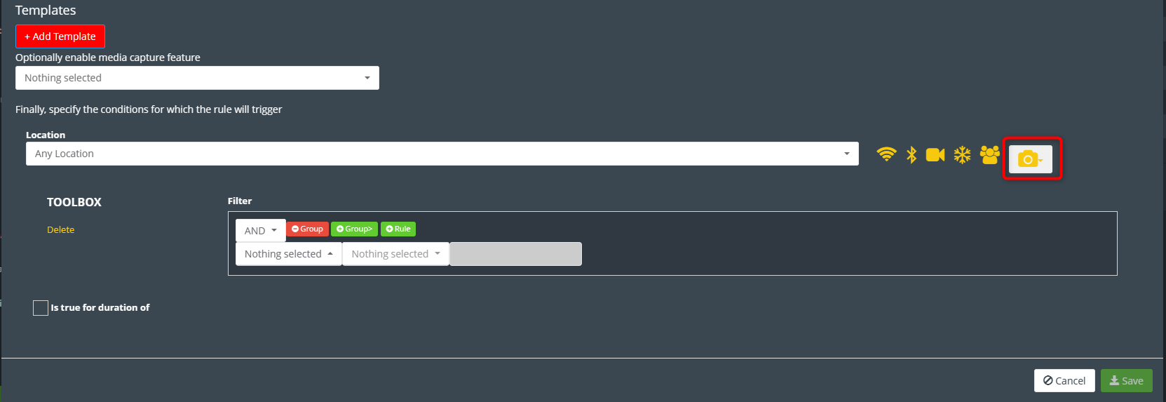
Create surveillance rules
Refer to the KloudInsights “Creating Rules
" section to learn how to create a rule. Alternatively, you can use the “Action Templates” section if you want to create an action template.
Use “Add Vision Entity Conditions” button to create vision rules.
Face Recognition Configuration
If you want to configure Face Recognition Configuration on your camera, you can do it using this feature.
Before you begin configuring the use cases, you should first configure the camera’s general configuration. Refer to the General Camera Configuration section for instructions.
Then, select the Face Recognition Configuration from the drop-down list.
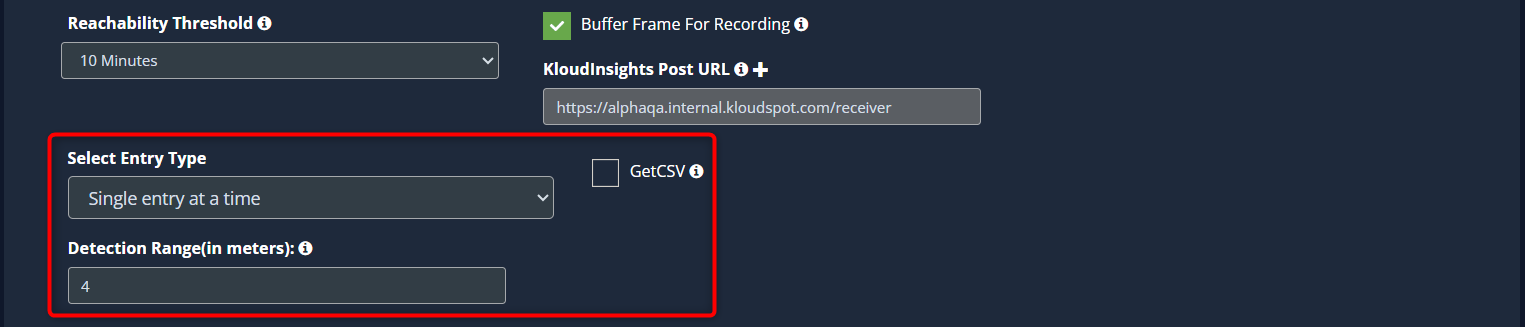
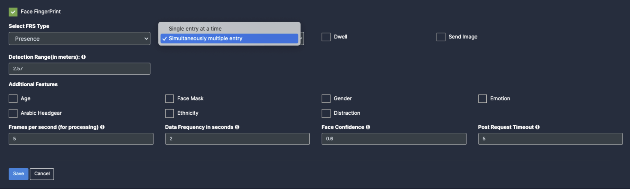
Scroll down and select the entry type. There are two entry modes available:
Single entry at a time: If this type is selected, only one face will be recognized at a time.
Simultaneous multiple entry: If this type is selected, it helps to recognize multiple faces at a time.
Specify the Detection Range (in meters). This setting allows you to specify the distance between the camera and the person you want to identify.
Check GetCSV Checkbox if you need CSV report of face recognition.
Other settings for face recognition should be set within KloudInsights. Refer to the Face Recognition System (FRS) manual to learn how to do this.
Draw ROI (region of interest) on the camera frame.
ROI in camera frames can help to improve efficiency, accuracy, and reduce storage requirements.
Here, ROI is optional. If ROI is not added, the model will detect the entire frame.
For Face Recognition, ROI can be drawn in two ways.
Using the polygon tool
Using the rectangle tool.
Refer to Draw ROI using the Polygon tool., Draw ROI using the rectangle
tool., and Monitor the camera view. Section from the Face
Detection for more details.
In this section, we will guide you through the process of adding and configuring cameras within the KloudVision platform. By following the step-by-step instructions provided, you will seamlessly bring your cameras online, enabling them to contribute to the generation of actionable analytics.
From defining regions of interest (ROIs) to adjusting camera settings for optimal performance, the Camera Setup and Configuration process empowers you to customize your surveillance network according to your specific requirements.
Subsections of Camera Setup and Configuration (NVIDIA)
Adding Cameras
In this section, we will guide you through the smooth incorporation of cameras into KloudVision. Incorporating cameras is more than just a physical setup; it symbolizes the merging of advanced technology and thoughtful strategy to establish a unified network of vigilant observers. Refer to the Camera Specifications document to select the appropriate camera for your needs.
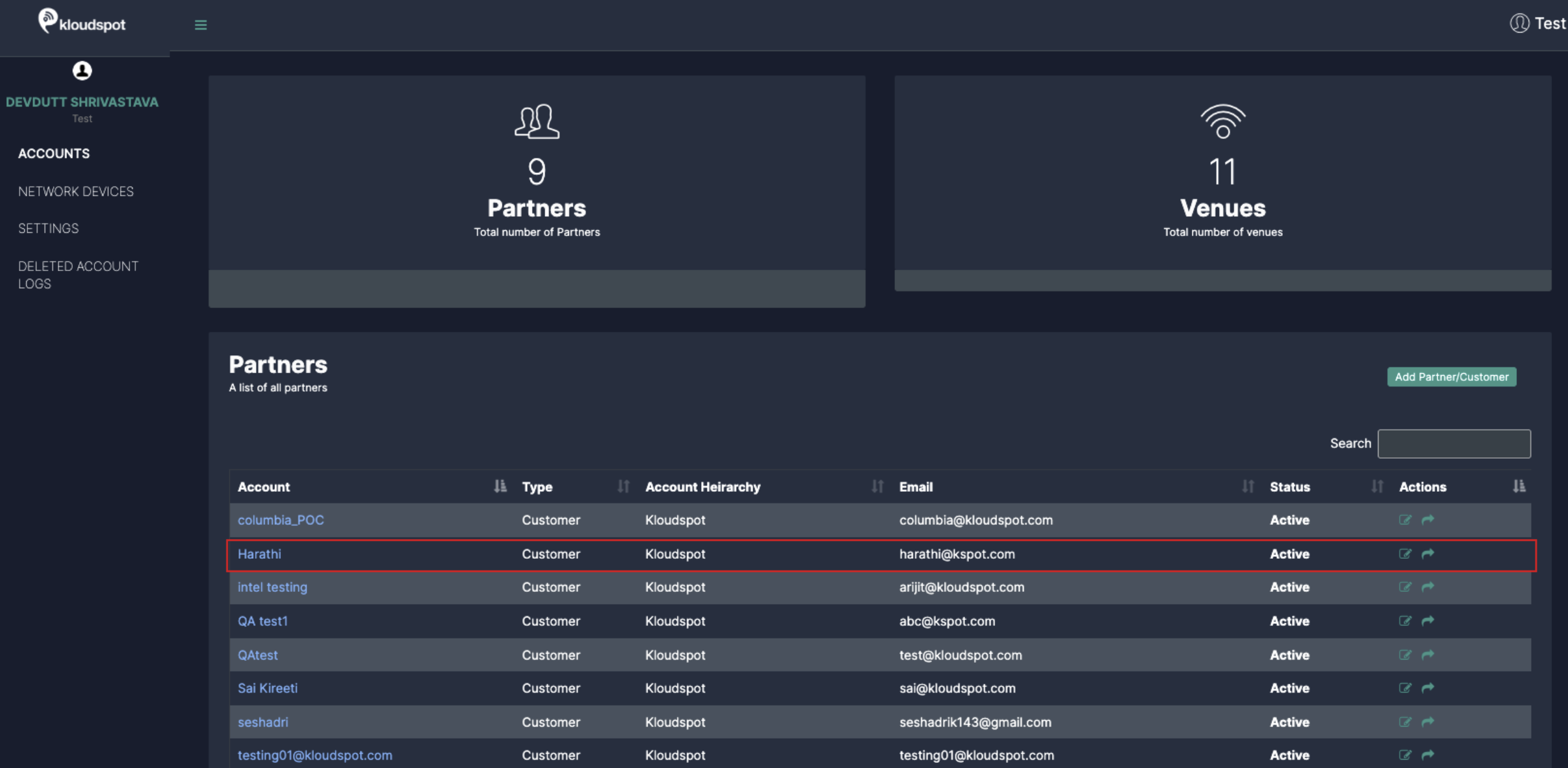
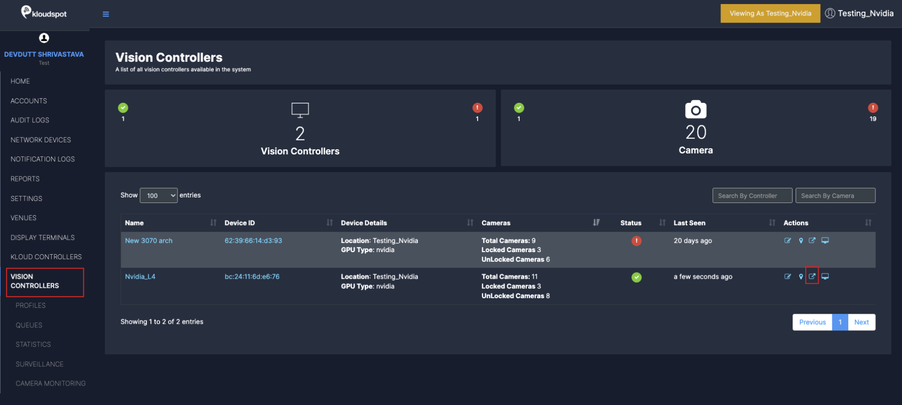
Once you have connected the controller, the next thing you need to do is to add the cameras to it. To do so, Click on the KloudManage and Choose your account.
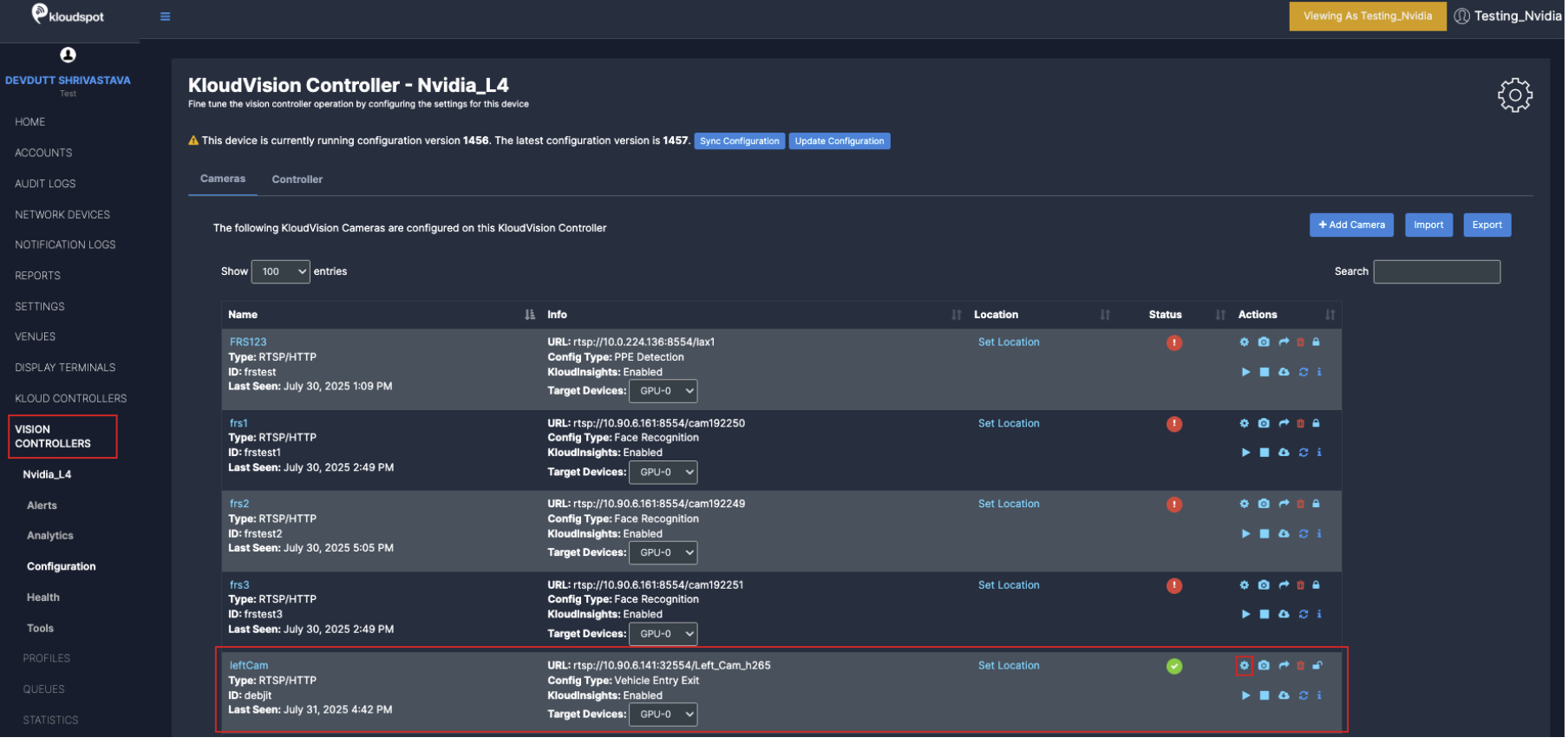
Navigate to VISION CONTROLLERS > Click on configuration icon for the desired controller.
In the window that opens click on the +Add Camera button
Enter the following in the popup window that opens and click the Save Changes button.
Name your camera.
  (We recommend naming your camera based on its location or
  using a clear, identifiable name for easy recognition)
Provide Unique ID for the Camera
(Assign a Unique ID to the camera for identification and management within the system)
Enter Camera Frames Per Seconds
(We recommend setting it to 25 FPS for optimal performance)
Choose the connection type (RTSP/HTTP or USB).
If we choose RTSP/HTTP we need to enter the URL you will link your camera feed from.
If using USB, provide the USB ID in the URL where the camera is connected (default is 0). (If unsure, please contact the Kloudspot Team for assistance.)
Select Codec based on the camera specifications (Refer to camera specifications)
Once the camera is configured, additional settings can be adjusted based on its intended use case.
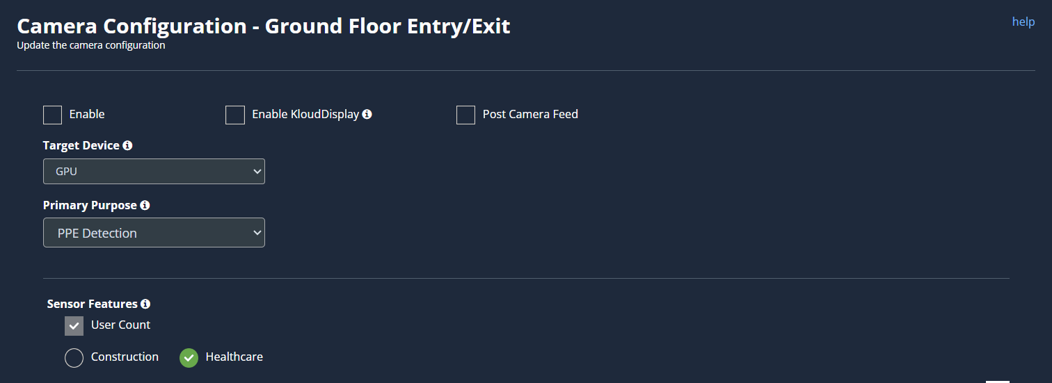
General Camera Configuration
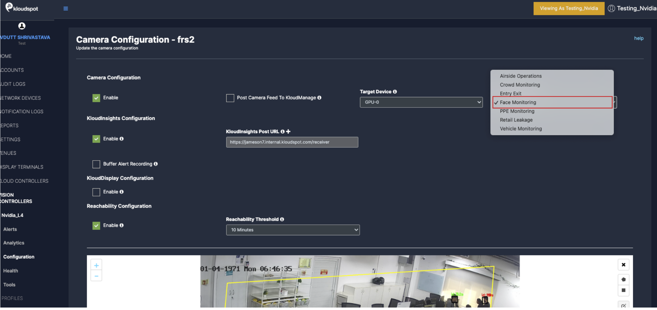
To configure general camera configuration, navigate to Vision Controller>(Select Controller configuration)
In the camera list that opens, click on the Configuration button next to the camera you want to configure. Immediately the camera configuration window will open.
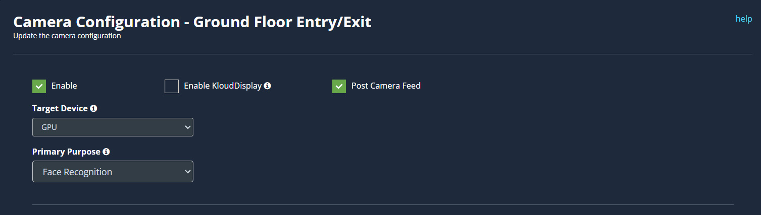
3. The configurations used as common in all use cases are given below.
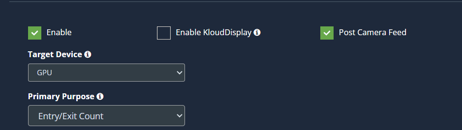
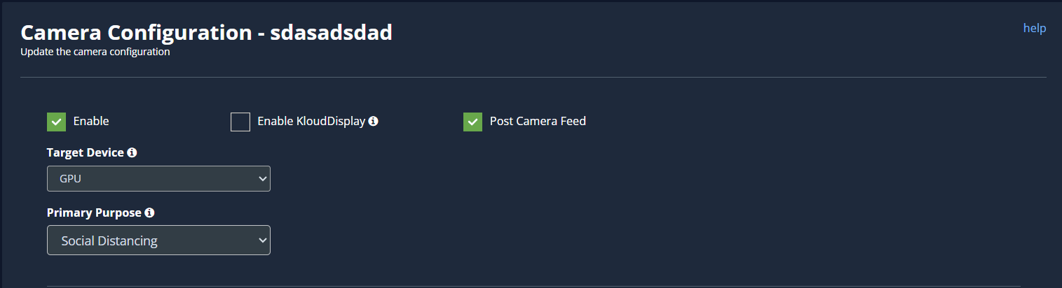
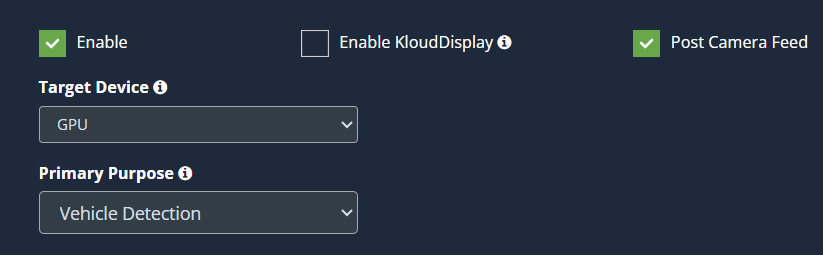
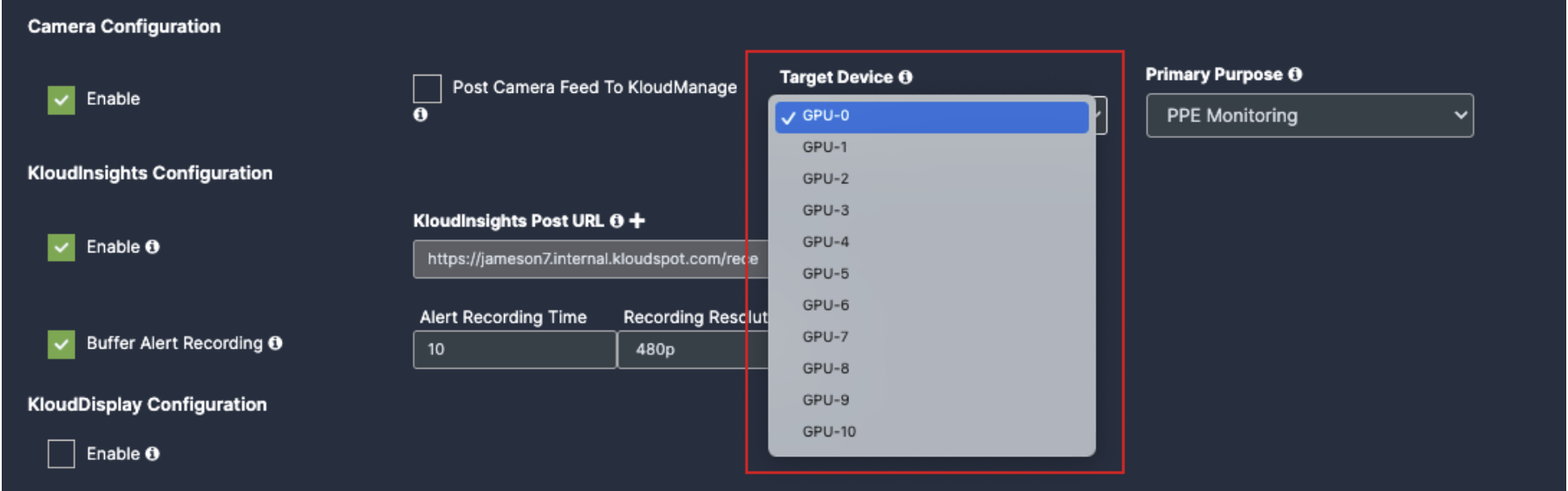
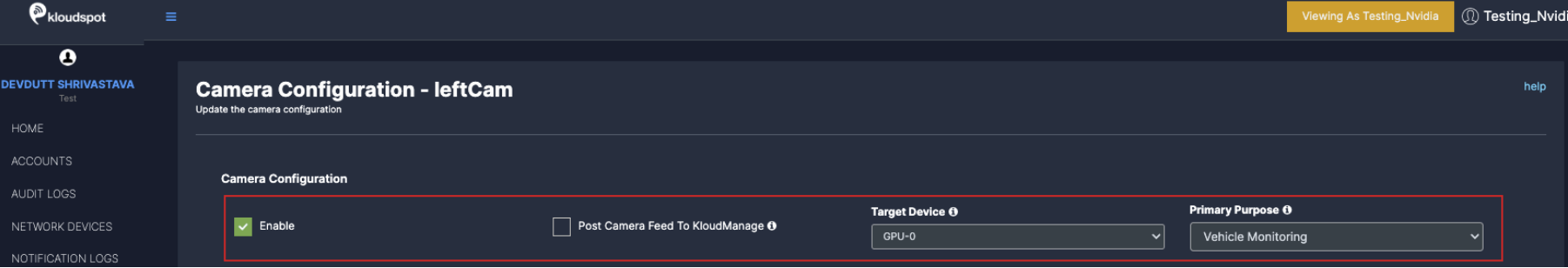
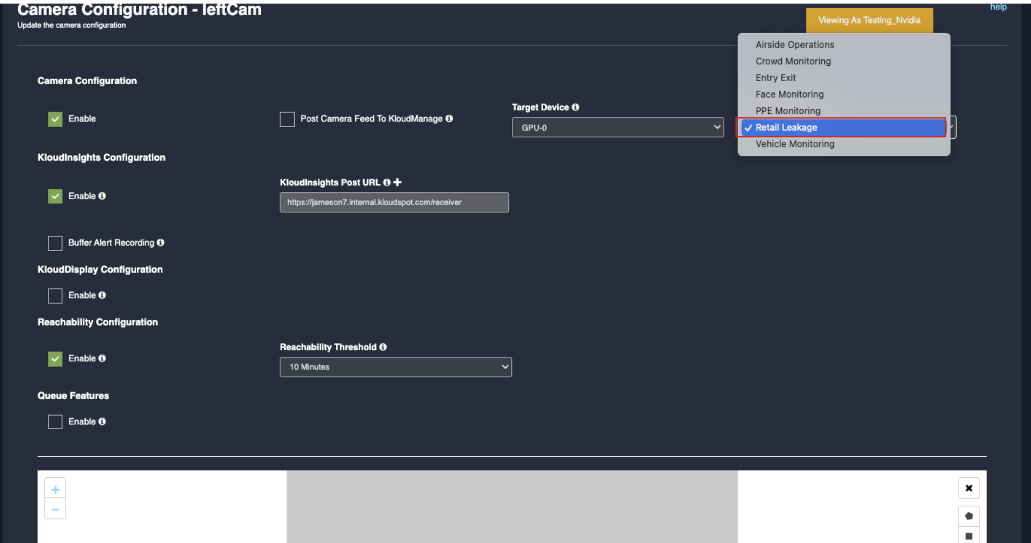
Enable: To activate any camera setup you desire, check enable checkbox.
Post Camera Feed: Enable this check box if you want to get camera status in KloudManage application.
Target device: Select GPU as per your controller specifications.
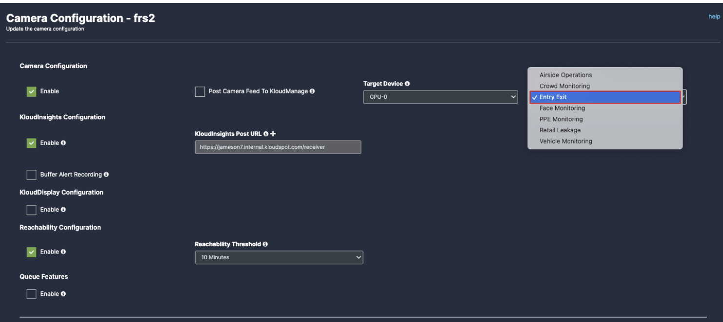
7. Primary Purpose: Select the detection Use case.
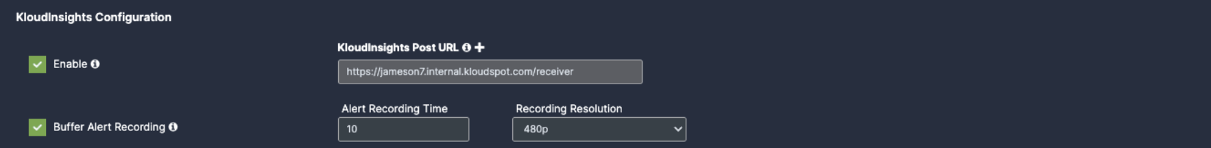
8. Enable KloudInsights: If you intend to share data from this camera with KloudInsights, please enable the designated checkbox. This will allow you to utilize the collected data to create new dashboards within the KloudInsights platform. Before proceeding, ensure integration between our Kloud Insights platform and KloudManage. Refer to the Integration with KloudManage section(Link) for detailed instructions on how to perform this integration.
KloudInsights Post URL: Enter your KloudInsights URL here.
Buffer Frame for Recording: Enable if you want a video/ image proof for the incidents happened, should have integration with KloudInsights.
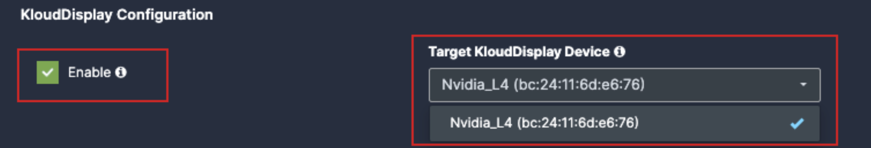
11. Enable KloudDisplay: Check this option to configure a KloudDisplay to react to the events generated by the camera. Click on the Target KloudDisplay dropdown to tie this camera with a KloudDisplay. Examples of this could be displaying a ‘Please wear a mask’ message on the display when the camera detects a person without a facemask.
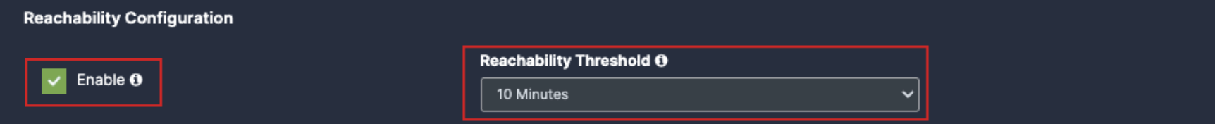
12. Reachability: It notifies you if the camera is inactive for an extended period. For example, If you set reachability to 10 you will get a notification if the camera is inactive for more than 10 minutes.
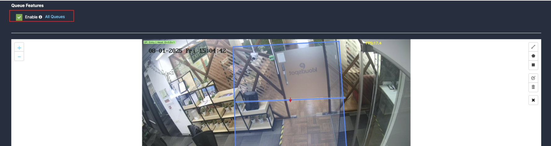
13. Queue feature: Enable the Queue checkbox for wait time and queue related data.(link queue)
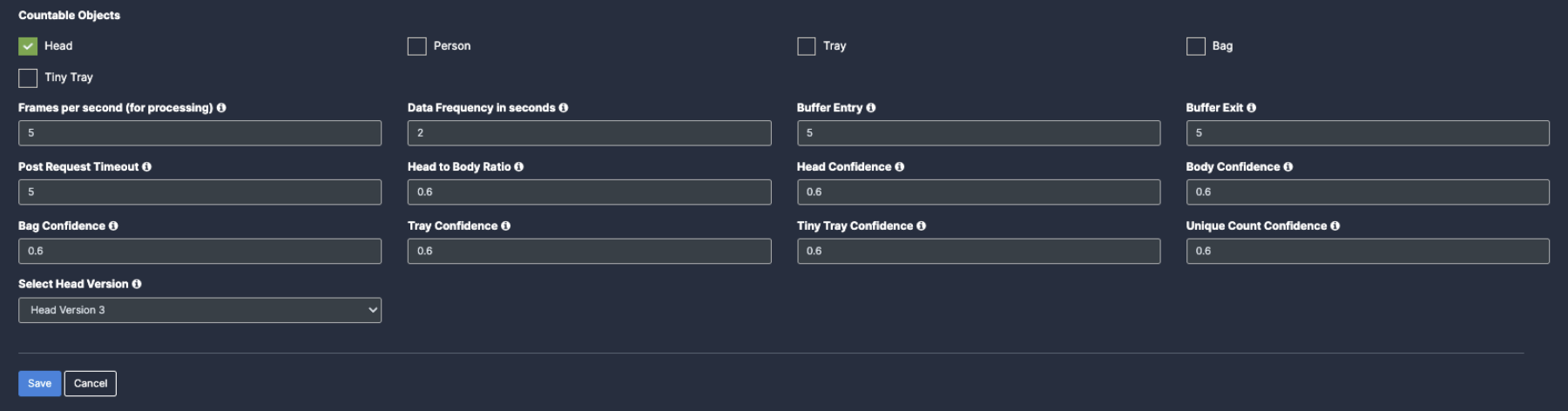
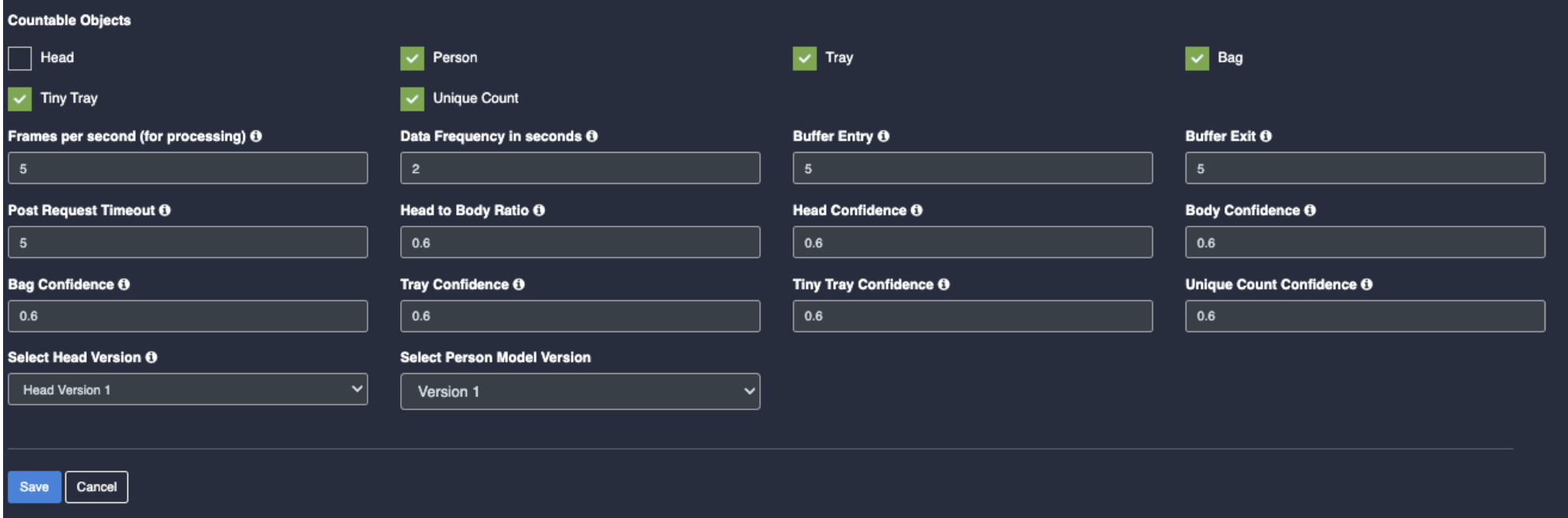
14. Countable objects:
Frames per second (for processing): These are the number of frames used by Vision Controller every second for data processing. KloudVision does not use all the frames emitted from the camera in a second. Higher values provided in this field may increase CPU/GPU usage.
Data Frequency in seconds: This value indicates how long Vision controller aggregates data before sending it out to KloudInsights. A lower value may increase the data frequency and result in a faster response. A higher value results in a delayed response.
Buffer Entry/Exit:
Post Request Timeout (in seconds): This value indicates how long KloudVision waits and retries to send the payloads out to KloudInsights until it reaches the preset timeout period.
Head to Body Ratio: Minimum head-to-body ratio required to classify a person as a child. If detected ratio meets/exceeds this value, the model identifies the individual as a child
Head Confidence: Minimum confidence score for head detection. Only detections scoring at or above this threshold are considered valid by the model.
Body Confidence: Minimum confidence score for person detection. Only detections scoring at or above this threshold are considered valid by the model
Bag Confidence: Minimum confidence score for bag detection. Only detections scoring at or above this threshold are considered valid by the model.
Tray Confidence: Minimum confidence score for tray detection. Only detections scoring at or above this threshold are considered valid by the model
Tiny Tray Confidence: Minimum confidence score for tiny tray detection. Only detections scoring at or above this threshold are considered valid by the model
Unique count Confidence: Minimum confidence required for the model to match two person detections as the same individual. Used for accurate unique person counting
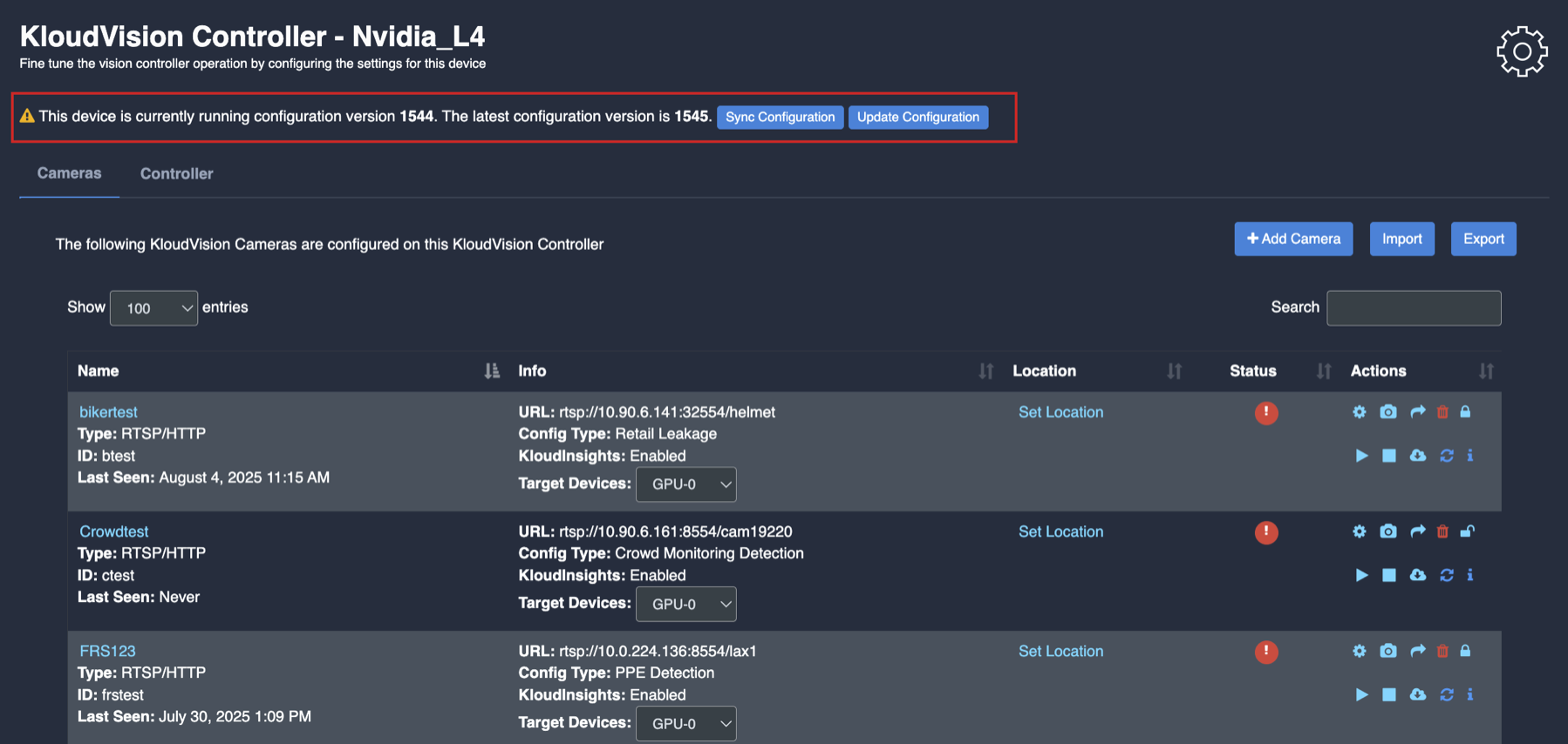
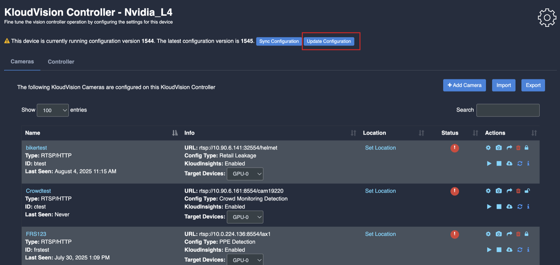
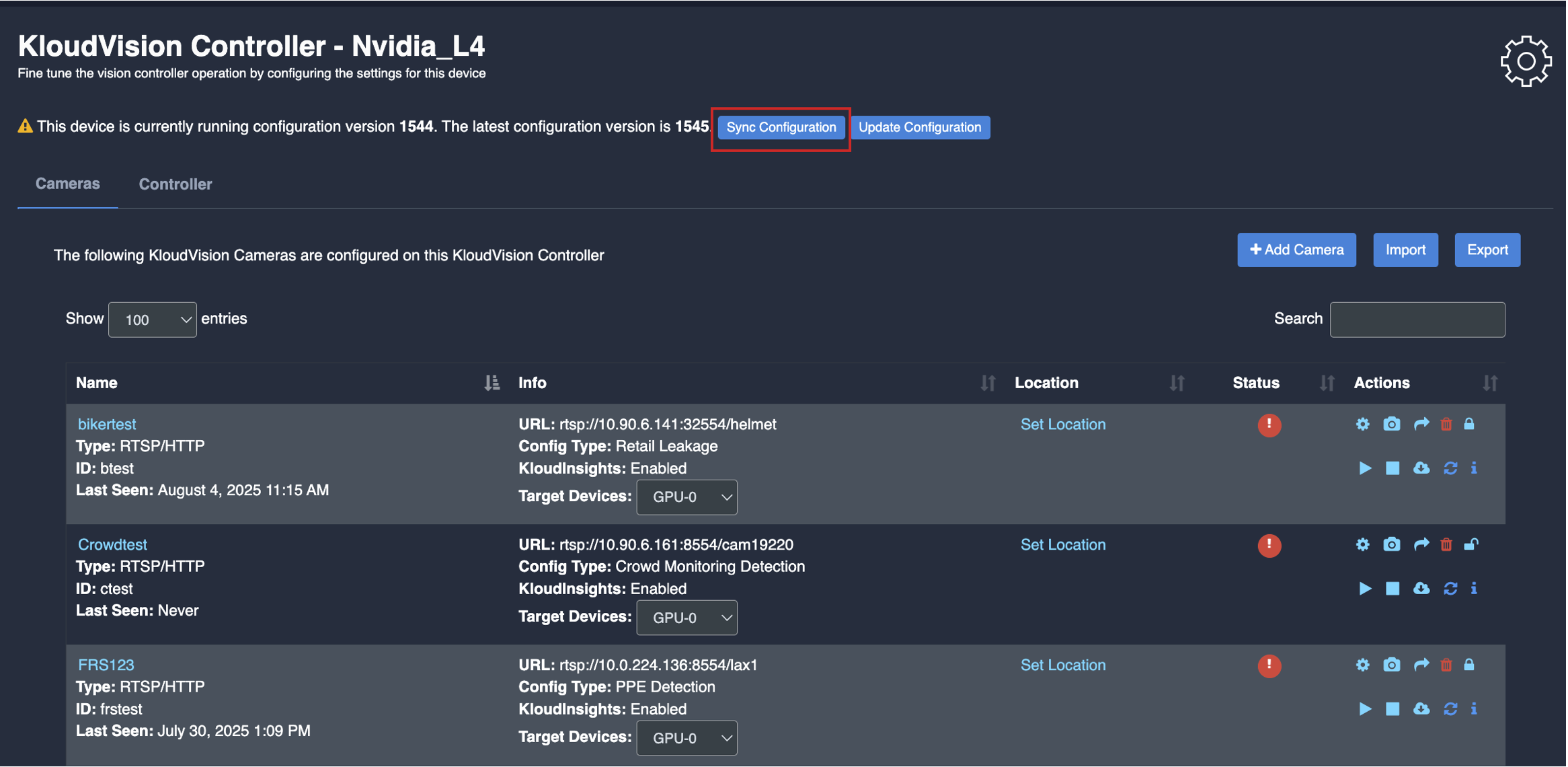
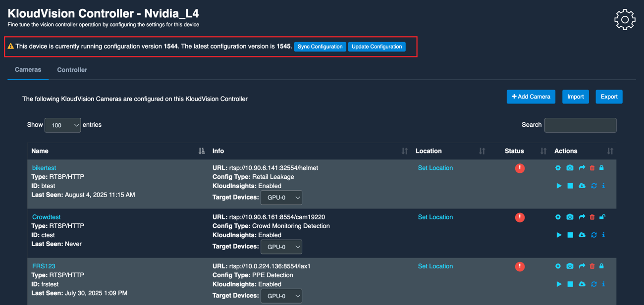
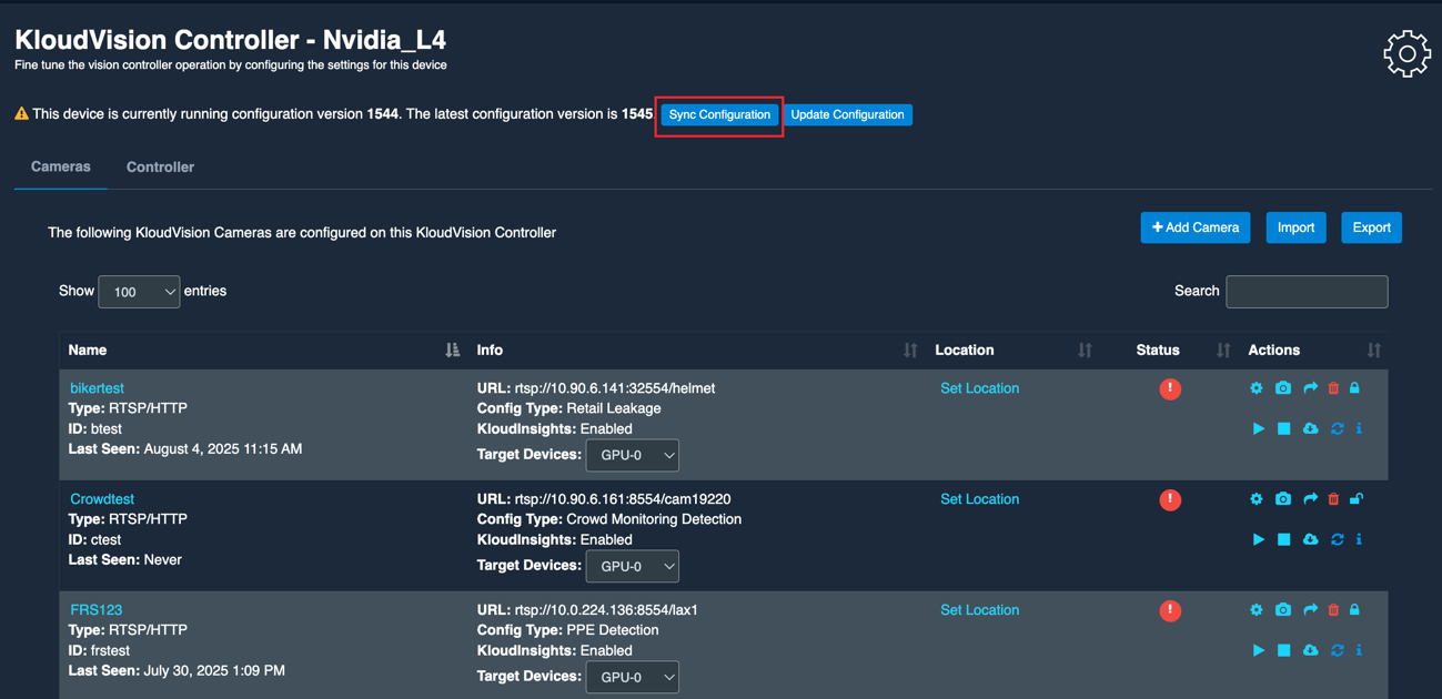
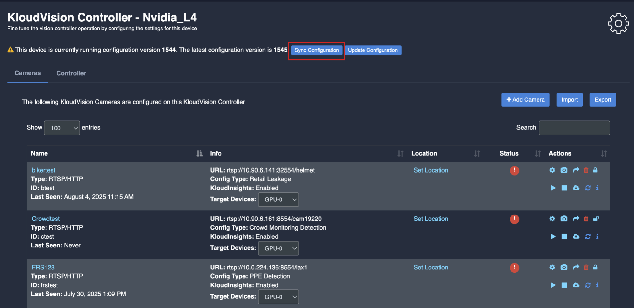
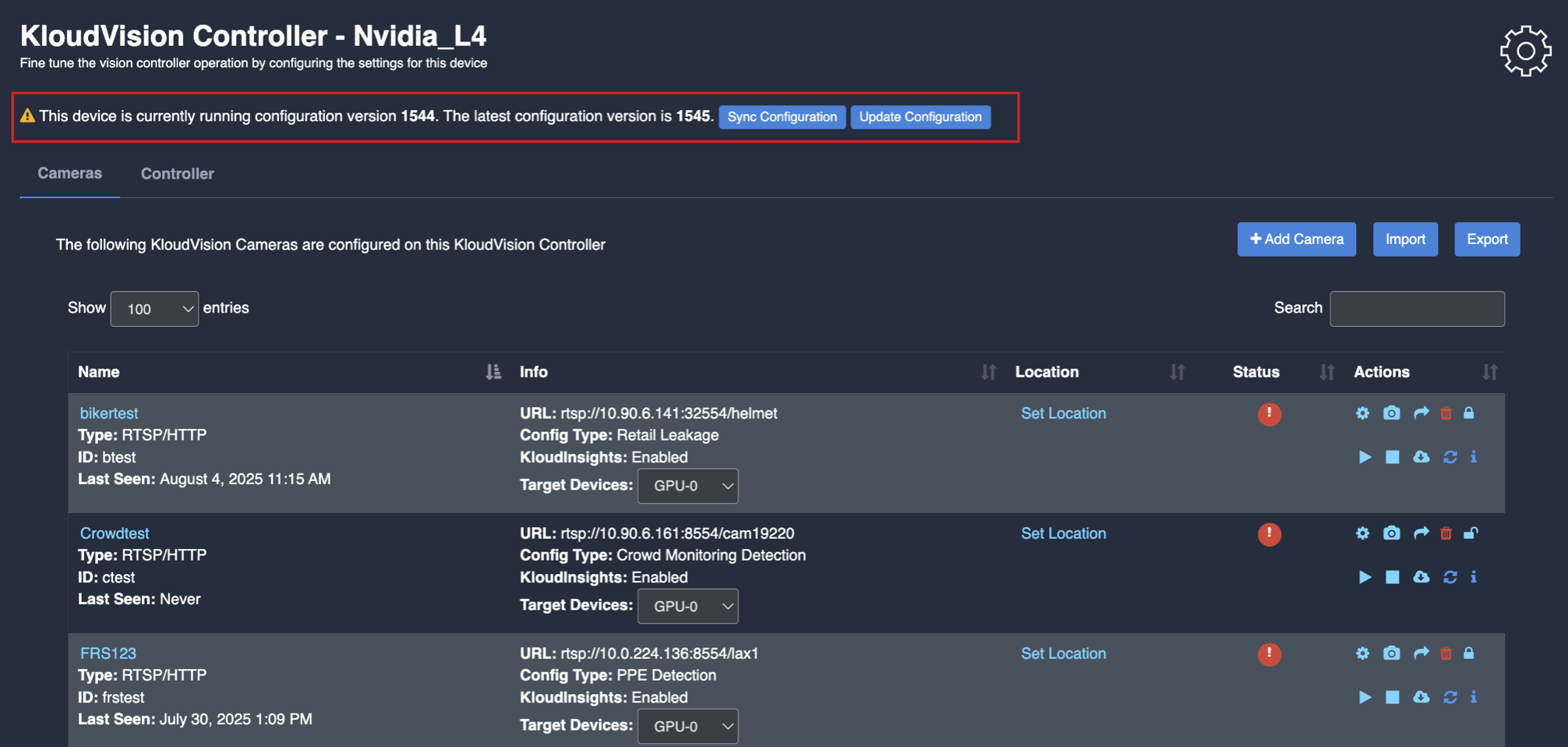
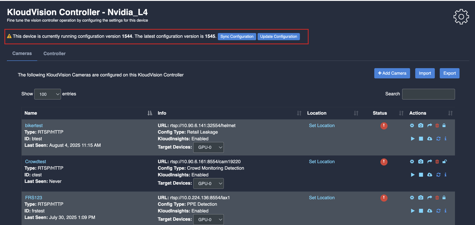
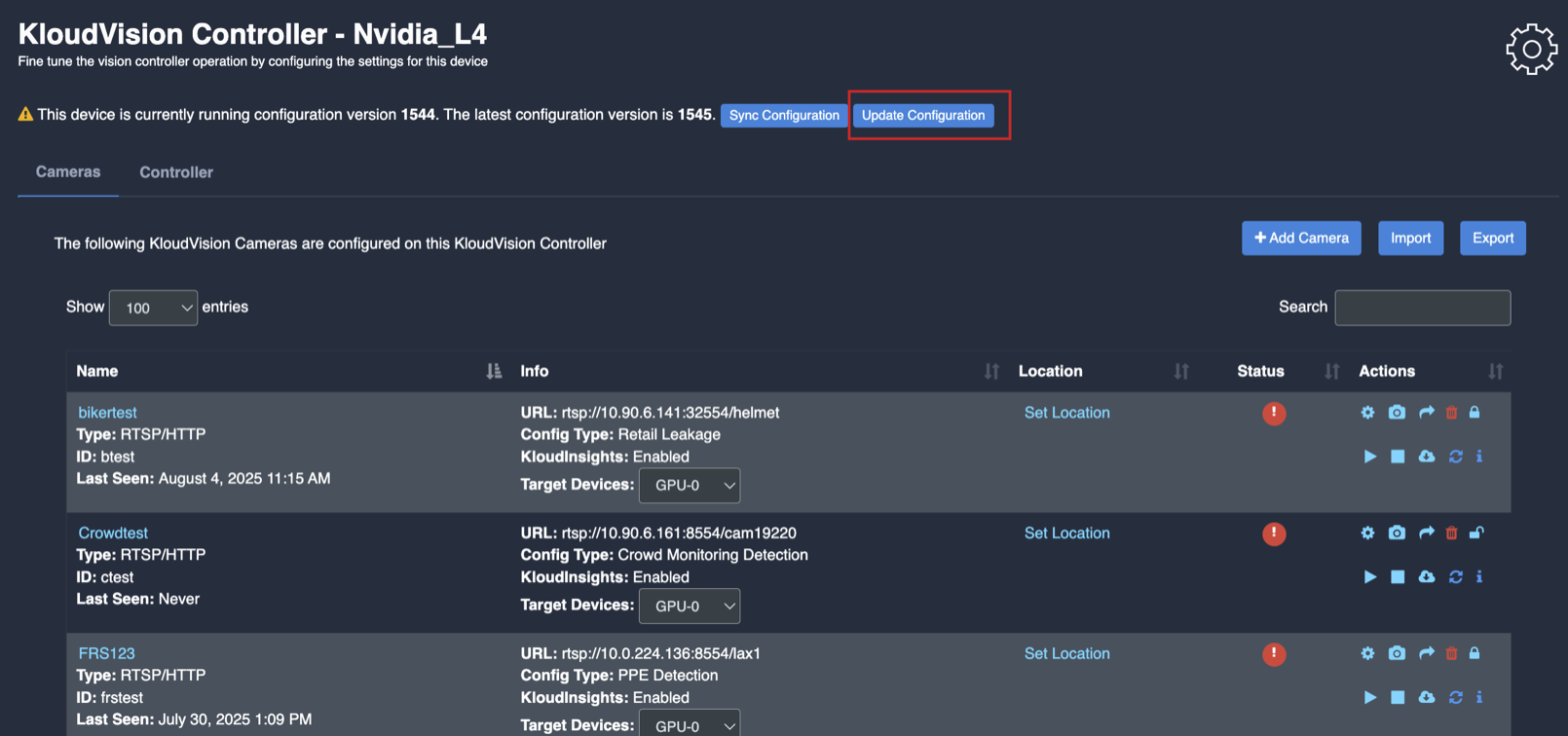
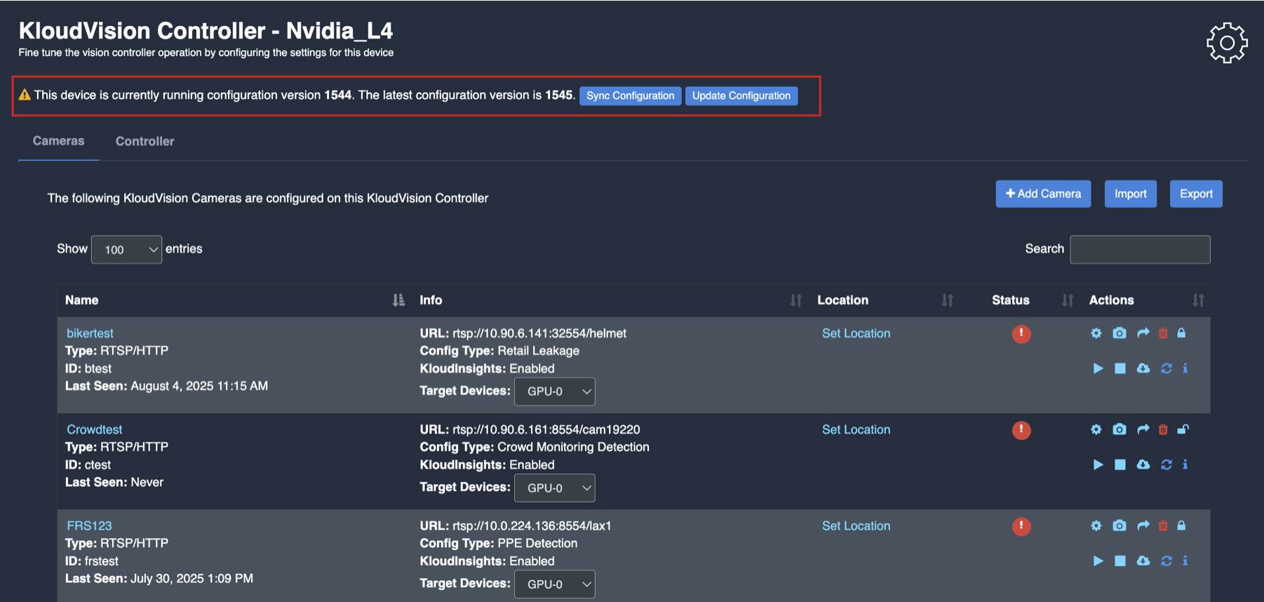
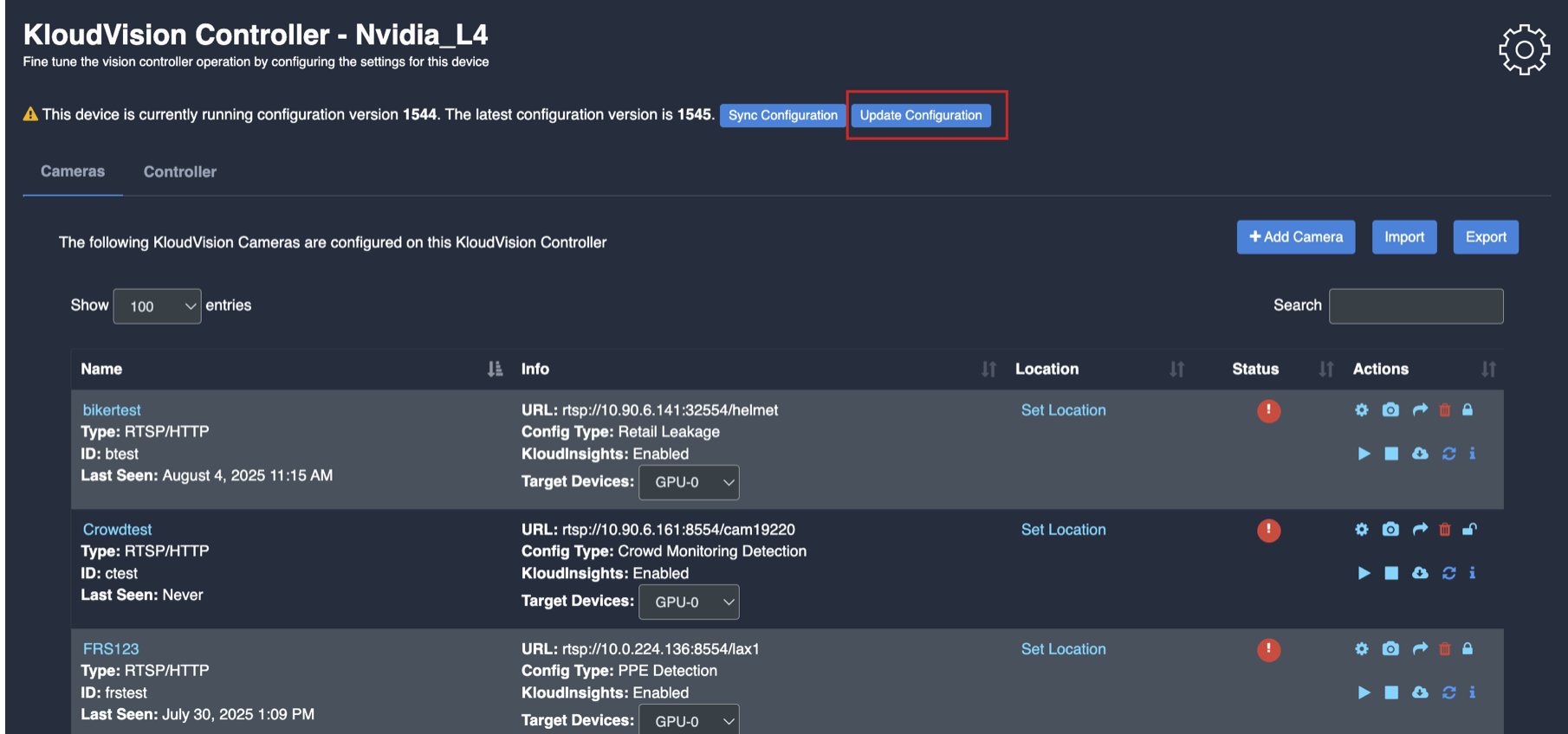
Update/ sync Configuration:
Once you perform any change in the controller or update any features/ use cases for camera you need to sync it.
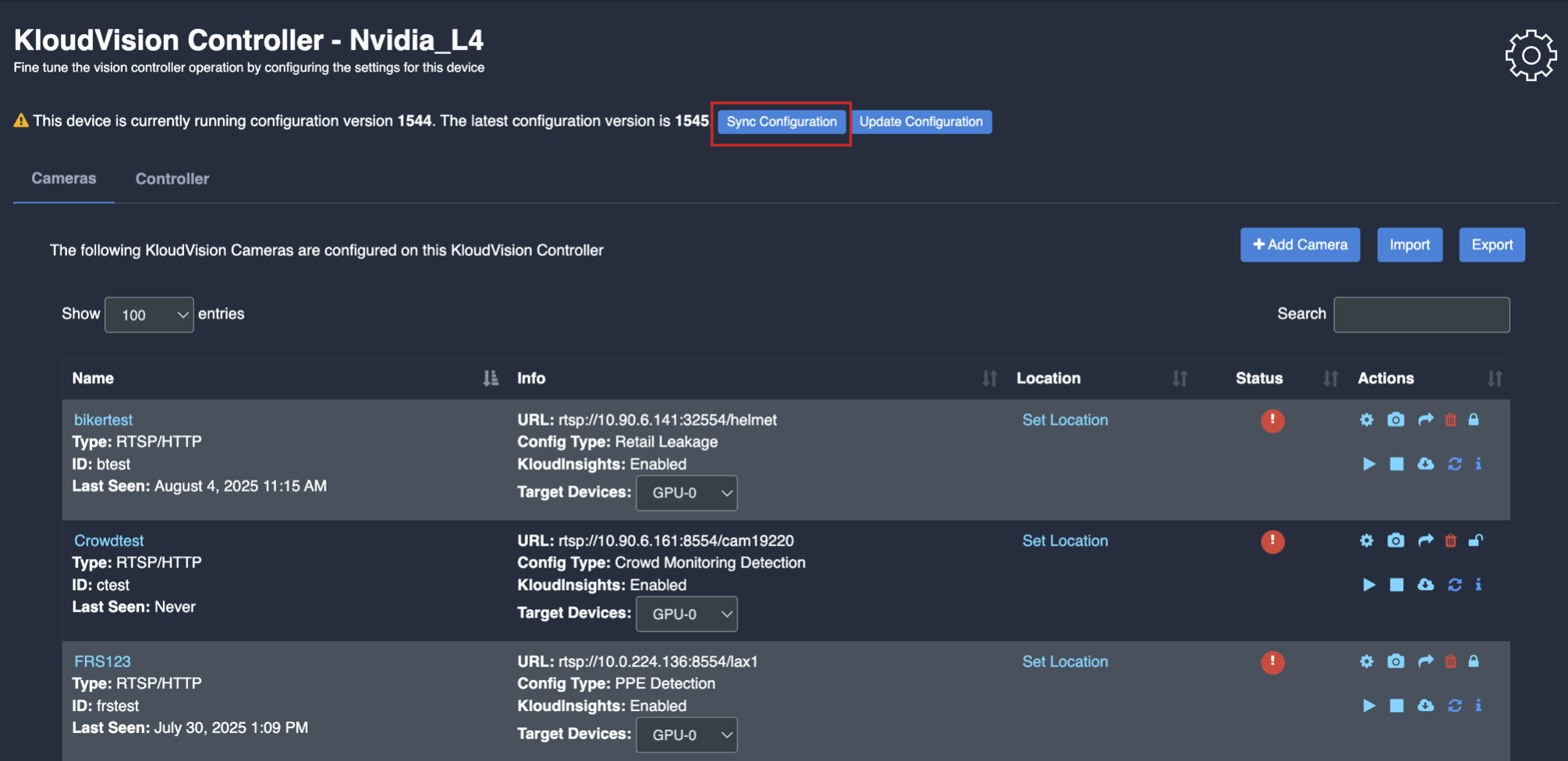
There are 2 types of syncing process:
Sync the configurations
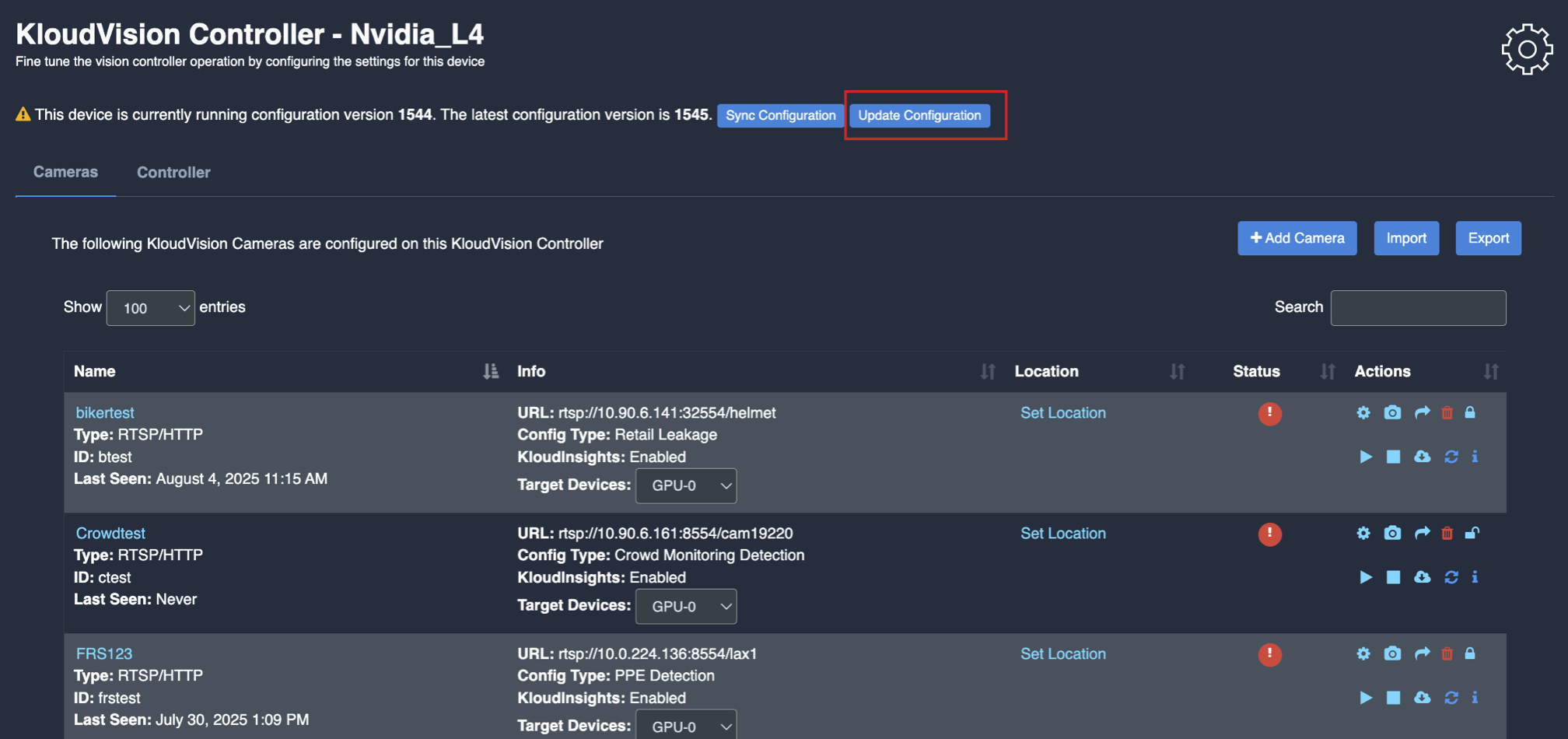
Update the Configurations
Click on sync configuration to restart the complete system syncing process. Basically for the initial camera setup and while any controller configuration update. (It will restart the docker and sync all the performed changes)
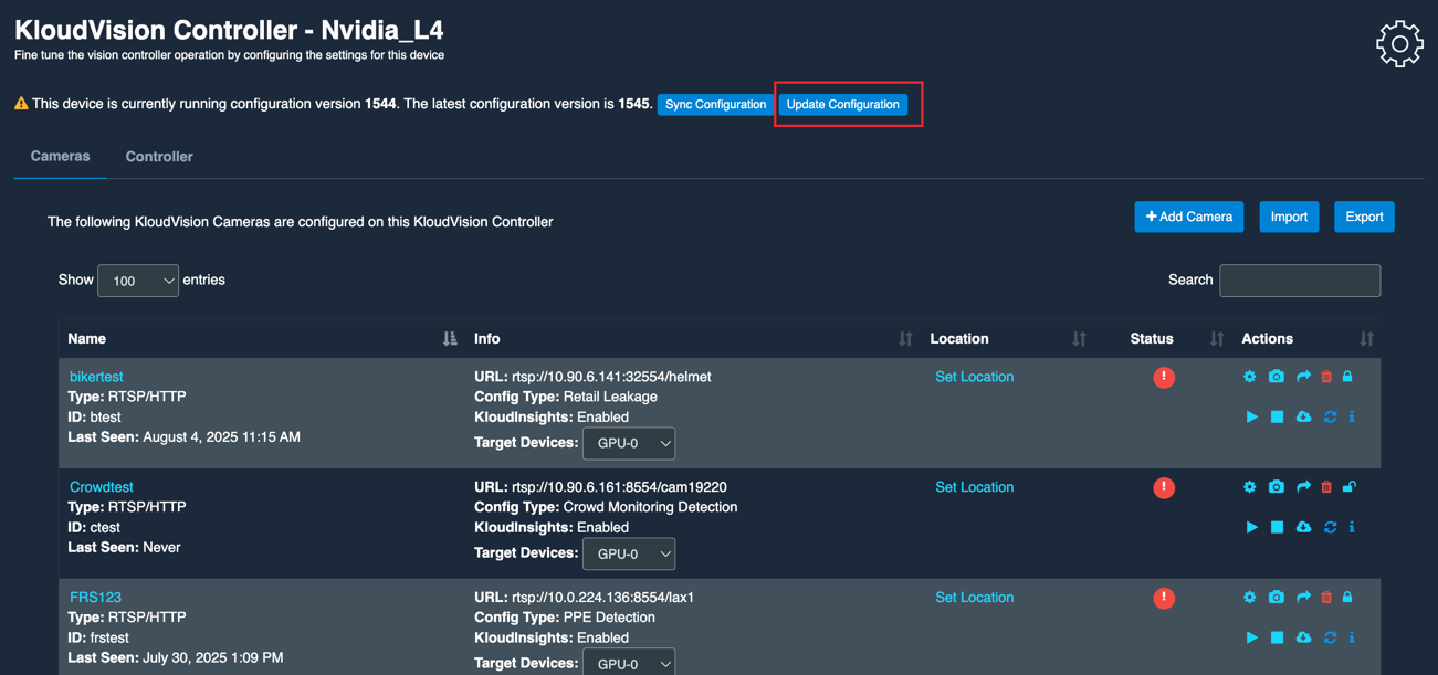
4. Click on the update configuration to recent changes in the system without any downtime. (General configuration sync)
Crowd Monitoring
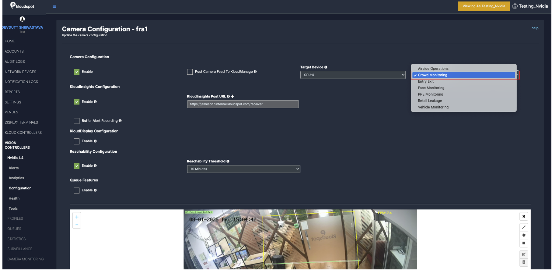
Before you begin configuring the use cases, you should first configure the camera’s general configuration. Refer to the General Camera Configuration section for instructions.
Then, select the Crowd Monitoring from the dropdown list
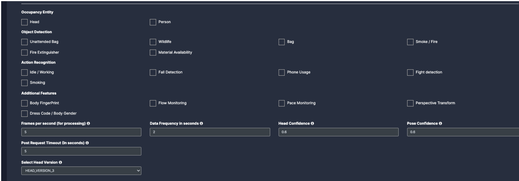
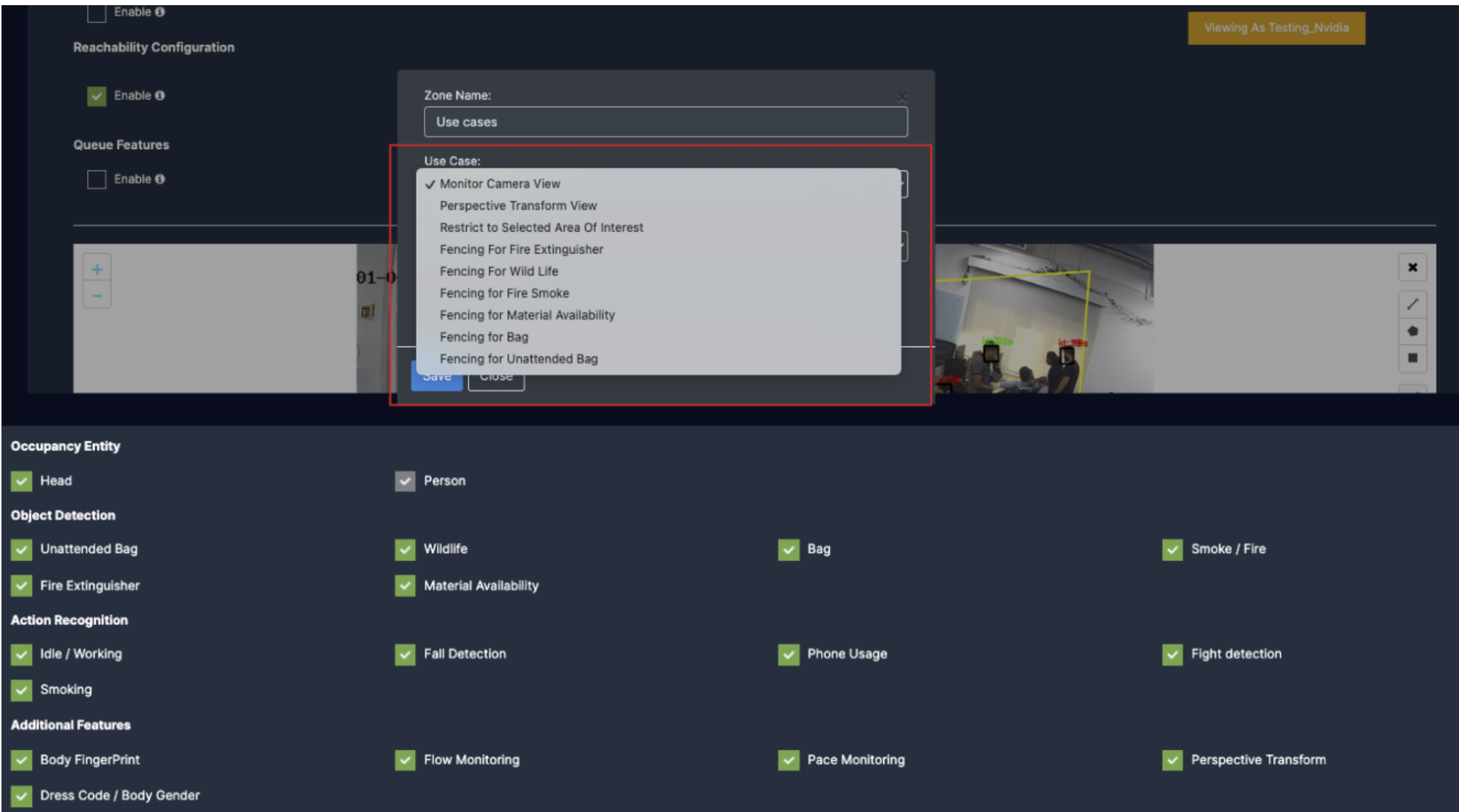
Next, Scroll down and choose your preferred use cases. You can choose multiple Features.
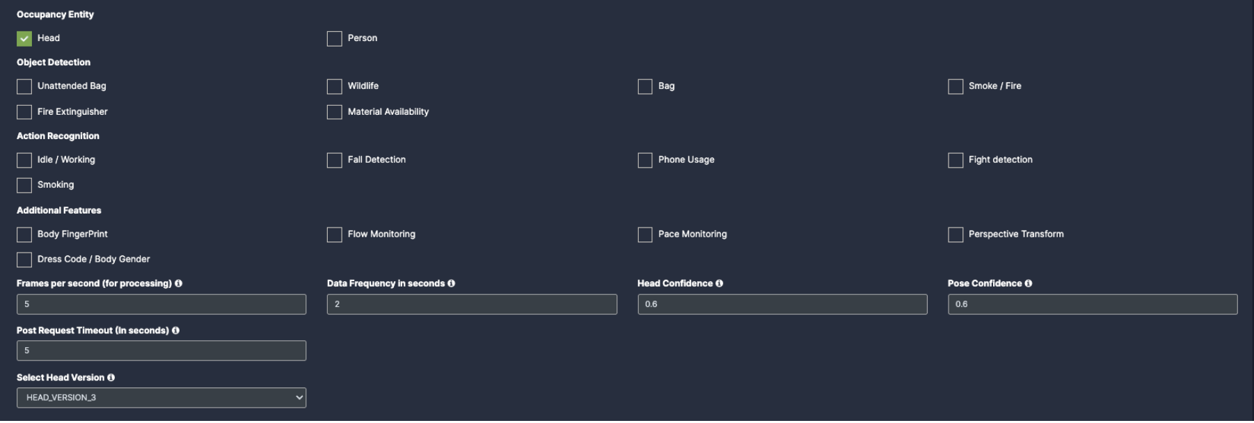
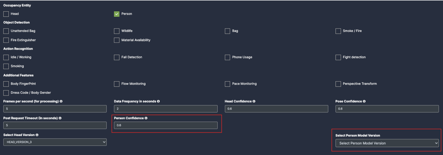
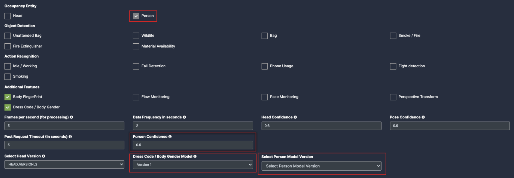
Occupancy Entity: (Exact number of people in the defined area)
Head: To capture any persons head count, click on this check box and fill the confidence rate for it.
Person: To capture any person count, click on this check box and fill the confidence rate and model version for it.
Object detection: (Identify known objects)
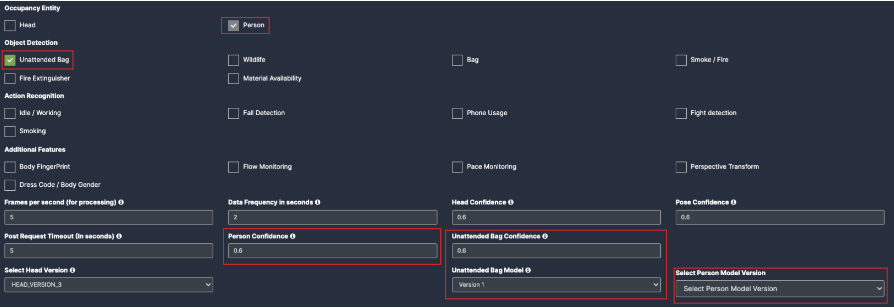
Unattended Bag: Once you click on the check box of unattended bag, the person will be auto enabled. You will see the Person confidence and version with bag model added below which needs to be filled.
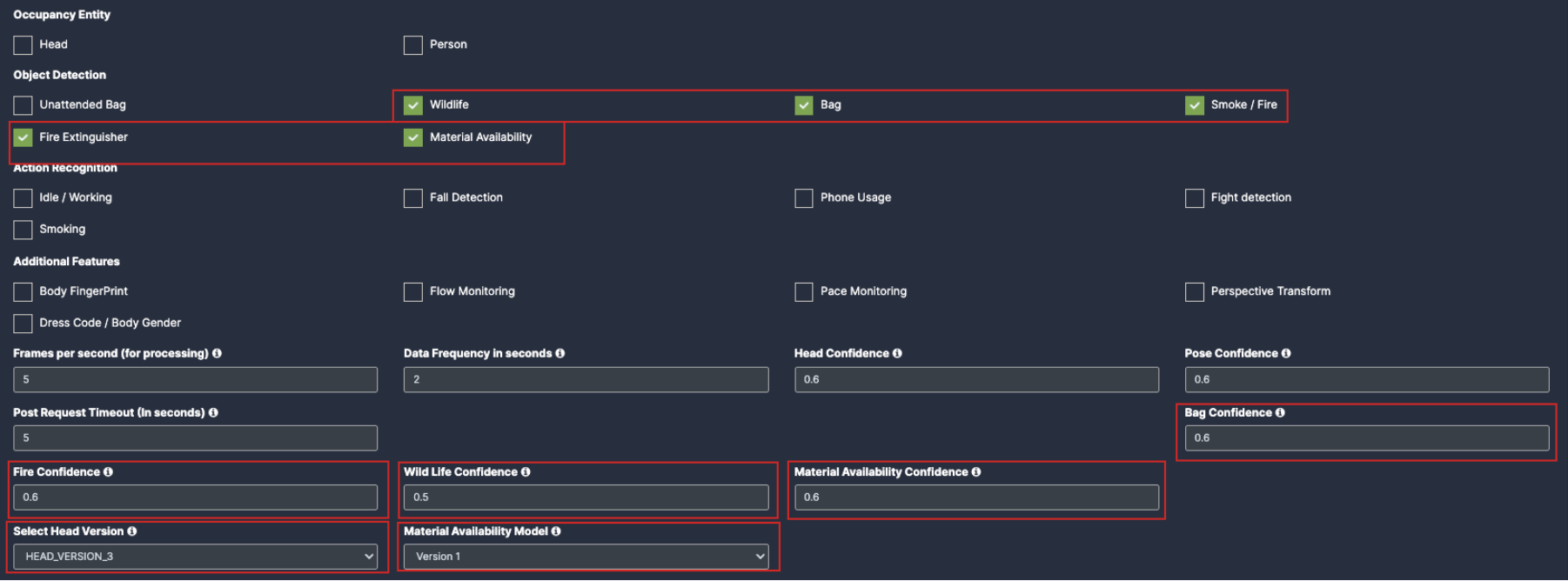
Wildlife: Once you click on the check box of wildlife their respective dropdowns will be added below for the respective feature detection.
Bag: Once you click on the check box of Bag their respective dropdowns will be added below for the respective feature detection.
Smoke/fire: Once you click on the check box of Smoke/fire their respective dropdowns will be added below for the respective feature detection.
Fire extinguisher: Once you click on the check box of Fire extinguisher their respective dropdowns will be added below for the respective feature detection.
Material Availability: Once you click on the check box of Material Availability their respective dropdowns will be added below for the respective feature detection.
Note: You need to Draw a separate ROI(Link) for all object detection Use cases.
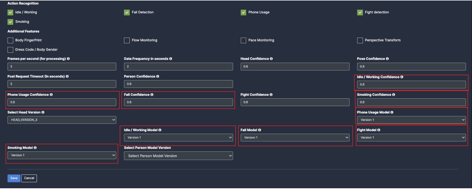
6. Action Recognition: (action a person (or object) is performing)
Idle/Working: Once you click on the check box of Idle/Working, the person checkbox will be auto enabled and their respective dropdowns will be added below for the respective feature detection.
Fall Detection: Once you click on the check box of fall detection, the person checkbox will be auto enabled and their respective dropdowns will be added below for the respective feature detection.
Phone usage: Once you click on the check box of Phone usage, the person checkbox will be auto enabled and their respective dropdowns will be added below for the respective feature detection.
Fight Detection: Once you click on the check box of Fight Detection, the person checkbox will be auto enabled and their respective dropdowns will be added below for the respective feature detection.
Smoking: Once you click on the check box of Smoking, the person checkbox will be auto enabled and their respective dropdowns will be added below for the respective feature detection.
Note: You need to Draw a separate ROI(Link) for all Action recognition Features.
Additional Features:
Body Fingerprint: Once you click on the check box of Body Fingerprint, the person checkbox will be auto enabled and their respective dropdowns will be added below.
Dress Code/ Body Gender: Once you click on the check box of Dress Code/ Body Gender, the person checkbox will be auto enabled and their respective dropdowns will be added below.
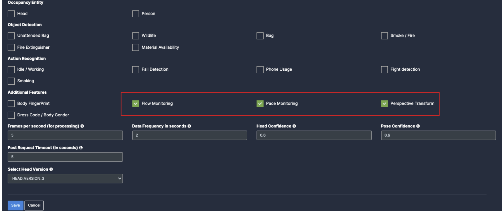
Flow Monitoring : Click on the check box of flow monitoring to enable the use case.
Pace Monitoring: Click on the check box of Pace monitoring to enable the use case.
Perspective Transform: Click on the check box of Perspective Transform to enable the use case.
Note: You need to Draw a separate ROI(Link) for all Additional features.
Draw ROI (region of interest) on the camera frame.
ROI in camera frames can help to improve efficiency, accuracy, and reduce storage requirements.
ROI must be added if kiosk mode is enabled. Otherwise, it is optional. If ROI is not added, the model will detect the entire frame.
For face detection, ROI can be drawn in two ways.
Using the polygon tool
Using the rectangle tool.
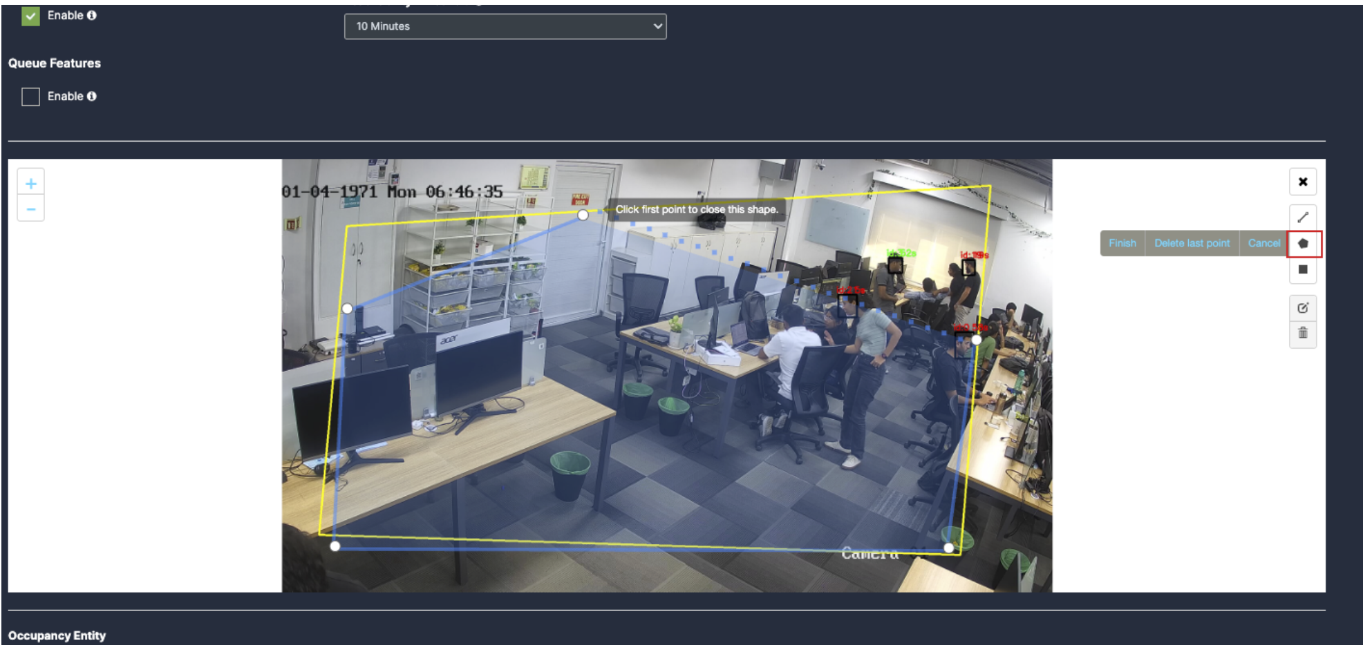
Draw ROI using the Polygon tool.
Click on the Polygon tool button from the camera frame.
Then connect the dots and draw the polygon in the space where you want to draw the ROI. It should have more than 2 points.
After drawing, click the Finish button to complete the drawing.
With this ROI you can achieve the below features:
Unattended bag
Wildlife
Bag
Smoke/Fire
Fire Extinguisher
Flow Monitoring
Perspective Transform
Material Availability
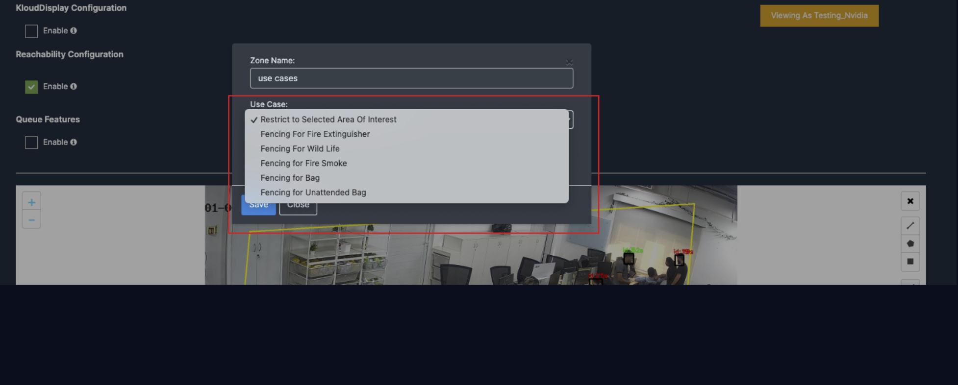
Enter the zone name in the popup window that opens and click the Save button.
New ROI zone added successfully.
Draw ROI using the rectangle tool.
Click on the Rectangle tool button from the camera frame.
Then draw the rectangle where you want to focus the camera.
Then enter the zone name and select Restrict to selected area of interest option from the dropdown list and click the Save button.
Detection will only happen when people enter this zone.
With this ROI you can achieve the below Features:
Object Detection
Action Recognition
Additional Features
Once the Use case Configuration is done, click on save.
Your Camera is configured for Crowd monitoring.
Update/ sync Configuration:
Once you perform any change in the controller or update any features/ use cases for camera you need to sync it.
There are 2 types of syncing process:
Sync the configurations
Update the Configurations
Click on sync configuration to restart the complete system syncing process. Basically for the initial camera setup and while any controller configuration update. (It will restart the docker and sync all the performed changes)
Click on the update configuration to recent changes in the system without any downtime. (General configuration sync)
Face Monitoring
Before you begin configuring the use cases, you should first configure the camera’s general configuration. Refer to the General Camera Configuration section for instructions.
Then, select the Face Monitoring from the dropdown list
Next, Scroll down and choose your preferred use cases. You can choose multiple Features.
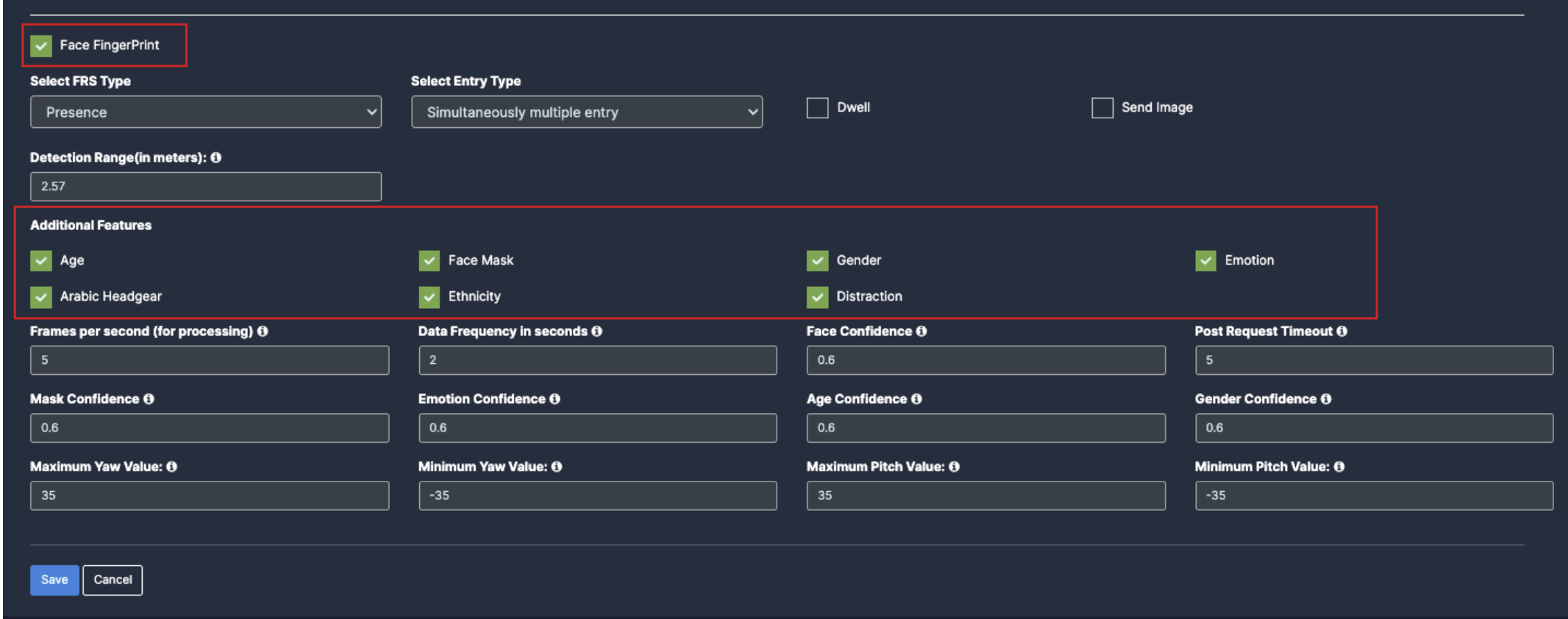
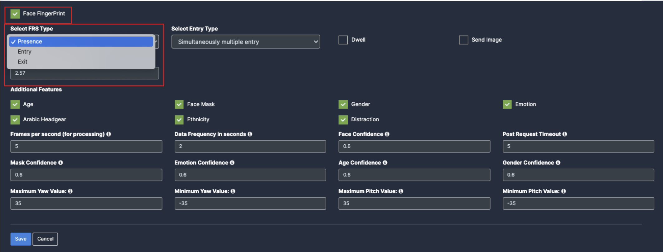
When you select the Face monitoring, Face fingerprint will be auto enabled.
Select the FRS type as per the location
Select the Entry type as per the use case requirement.
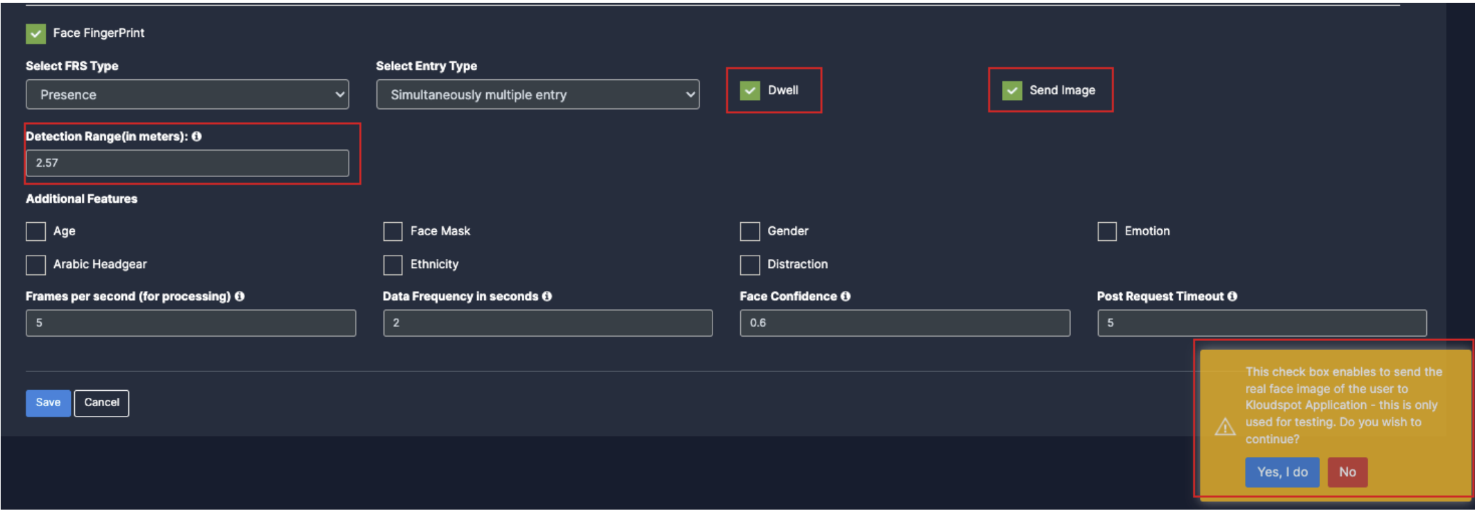
You can enable dwell time as per the requirement. (ex: enable if the camera is for main gate.)
You can enable Send Image for all the faces for testing purpose.
You can also select the Detection Range(in meters) as per the camera and gate distance.
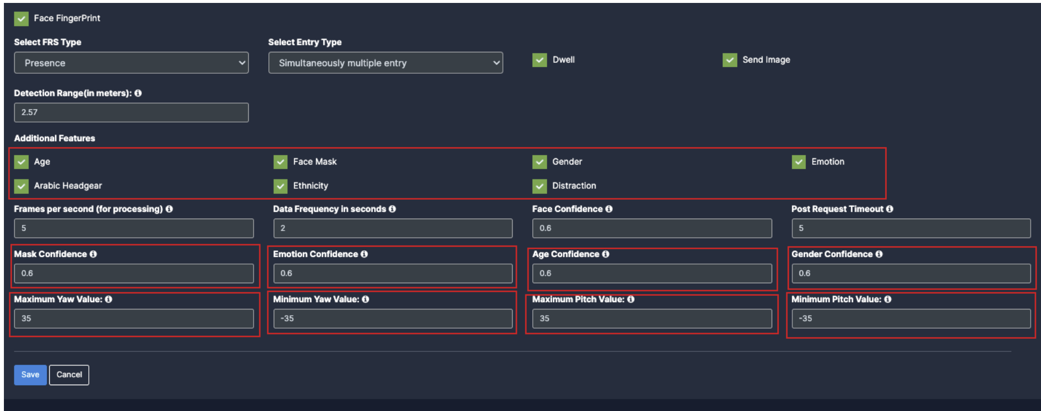
5. Additional Features: -
Age: Once you enable the checkbox of Age, their respective dropdowns will be added below for the respective feature detection.
Face mask: Once you enable the checkbox of Face mask, their respective dropdowns will be added below for the respective feature detection.
Gender: Once you enable the checkbox of Gender, their respective dropdowns will be added below for the respective feature detection.
Emotion: Once you enable the checkbox of Emotion, their respective dropdowns will be added below for the respective feature detection.
Arabic headgear: Once you enable the checkbox of Arabic headgear, their respective dropdowns will be added below for the respective feature detection.
Ethnicity: Once you enable the checkbox of Ethnicity, their respective dropdowns will be added below for the respective feature detection.
Distraction: Once you enable the checkbox of Distraction, their respective dropdowns will be added below for the respective feature detection.
Draw ROI (region of interest) on the camera frame.
ROI in camera frames can help to improve efficiency, accuracy, and reduce storage requirements.
ROI must be added if kiosk mode is enabled. Otherwise, it is optional. If ROI is not added, the model will detect the entire frame.
For face detection, ROI can be drawn in two ways.
Using the polygon tool
Using the rectangle tool.
Draw ROI using the Polygon tool.
Click on the Polygon tool button from the camera frame.
Then connect the dots and draw the polygon in the space where you want to draw the ROI. It should have more than 2 points.
9. After drawing, click the Finish button to complete the drawing.
8. Enter the zone name in the popup window that opens and click the Save button.
New ROI zone added successfully.
Draw ROI using the rectangle tool.
Click on the Rectangle tool button from the camera frame.
Then draw the rectangle where you want to focus the camera.
8. Then enter the zone name and select Restrict to selected area of interest option from the dropdown list and click the Save button.
Detection will only happen when people enter this zone.
With this ROI you can achieve the below Features:
Face Fingerprint
Additional Features
Once the Use case Configuration is done, click on save.
Your Camera is configured for face monitoring.
Update/ sync Configuration:
Once you perform any change in the controller or update any features/ use cases for camera you need to sync it.
There are 2 types of syncing process:
Sync the configurations
Update the Configurations
Click on sync configuration to restart the complete system syncing process. Basically for the initial camera setup and while any controller configuration update. (It will restart the docker and sync all the performed changes)
Click on the update configuration to recent changes in the system without any downtime. (General configuration sync)
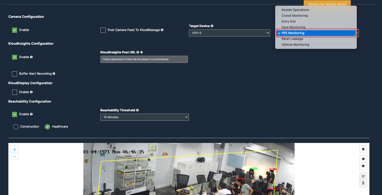
PPE Monitoring
Before you begin configuring the use cases, you should first configure the camera’s general configuration. Refer to the General Camera Configuration section for instructions.
Then, select the PPE Monitoring from the dropdown list
6. There will be checkboxes for Construction and Healthcare. Selecting either checkbox will display the corresponding dropdown options below.
7. Choose construction, Scroll down and choose your preferred use cases. You can choose multiple Features.
8. Now Choose Healthcare, scroll down and choose your preferred use cases. You can choose multiple Features.
Draw ROI (region of interest) on the camera frame.
ROI in camera frames can help to improve efficiency, accuracy, and reduce storage requirements.
ROI must be added if kiosk mode is enabled. Otherwise, it is optional. If ROI is not added, the model will detect the entire frame.
For face detection, ROI can be drawn in two ways.
Using the polygon tool
Using the rectangle tool.
Draw ROI using the Polygon tool.
Click on the Polygon tool button from the camera frame.
Then connect the dots and draw the polygon in the space where you want to draw the ROI. It should have more than 2 points.
15. After drawing, click the Finish button to complete the drawing.
8. Enter the zone name in the popup window that opens and click the Save button.
9. New ROI zone added successfully.
Draw ROI using the rectangle tool.
Click on the Rectangle tool button from the camera frame.
Then draw the rectangle where you want to focus the camera.
Then enter the zone name and select Restrict to selected area of interest option from the dropdown list and click the Save button.
9. Detection will only happen when people enter this zone.
10. With this ROI you can achieve the below Features:
All Additional Features
Once the Use case Configuration is done, click on save.
Your Camera is configured for PPE monitoring.
Update/ sync Configuration:
Once you perform any change in the controller or update any features/ use cases for camera you need to sync it.
There are 2 types of syncing process:
Sync the configurations
Update the Configurations
Click on sync configuration to restart the complete system syncing process. Basically for the initial camera setup and while any controller configuration update. (It will restart the docker and sync all the performed changes)
4. Click on the update configuration to recent changes in the system without any downtime. (General configuration sync)
Entry/Exit Count Configuration
Before you begin configuring the use cases, you should first configure the camera’s general configuration. Refer to the General Camera Configuration section for instructions.
Then, select the Entry/ Exit from the dropdown list
Scroll down and choose your preferred use cases. You can choose multiple Features.
Countable Objects: (Physical items or entities that can be individually identified and counted)
Head: Enable the checkbox of Head as per your feature requirement.
Person: Once you enable the checkbox of Face mask, their respective dropdowns and Unique count checkbox will be added below for the respective feature detection.
Tray: Enable the checkbox of Tray as per your feature requirement for the respective feature detection.
Bag: Enable the checkbox of Bag as per your feature requirement for the respective feature detection.
Tiny Tray: Enable the checkbox of Tiny Tray as per your feature requirement for the respective feature detection.
Unique Count: Enable the checkbox of Unique Count as per your feature requirement
Draw ROI (region of interest) on the camera frame.
ROI in camera frames can help to improve efficiency, accuracy, and reduce storage requirements.
ROI must be added if kiosk mode is enabled. Otherwise, it is optional. If ROI is not added, the model will detect the entire frame.
For face detection, ROI can be drawn in two ways.
Using the Line
Using the polygon tool
Using the rectangle tool.
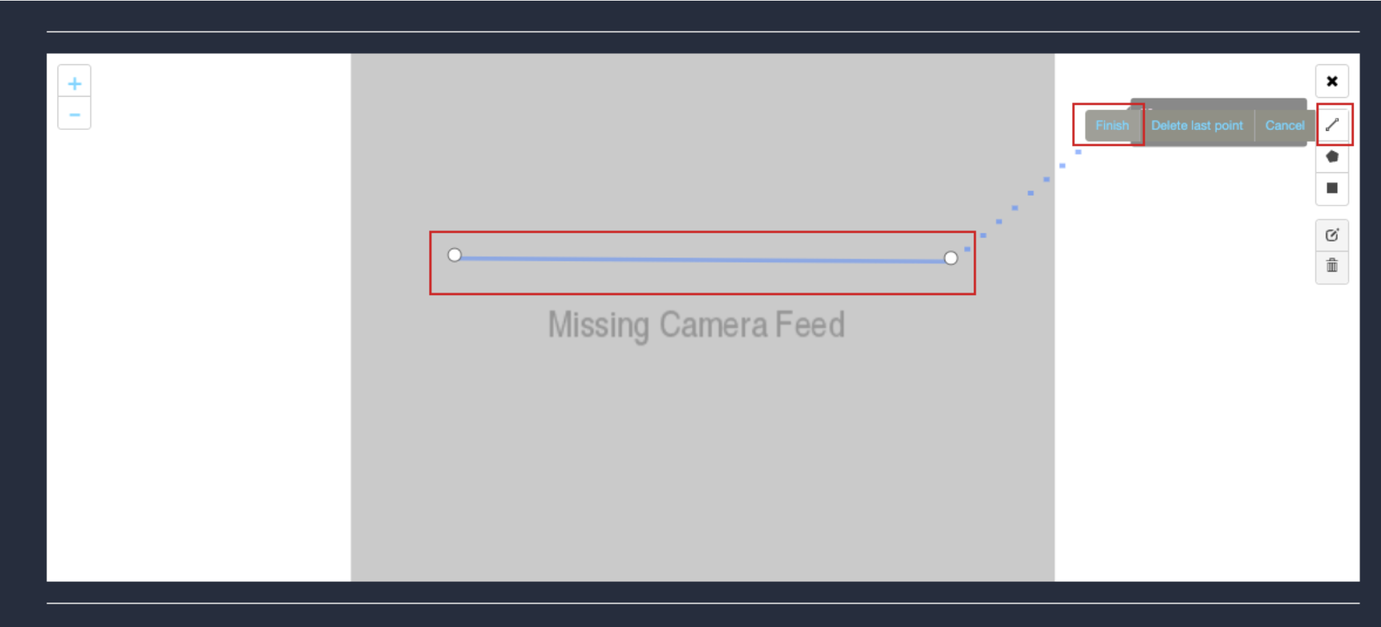
Draw ROI using the line tool.
Click on the Line tool button from the camera frame.
Then draw a straight line on the camera feed.
After drawing, click the Finish button to complete the drawing.
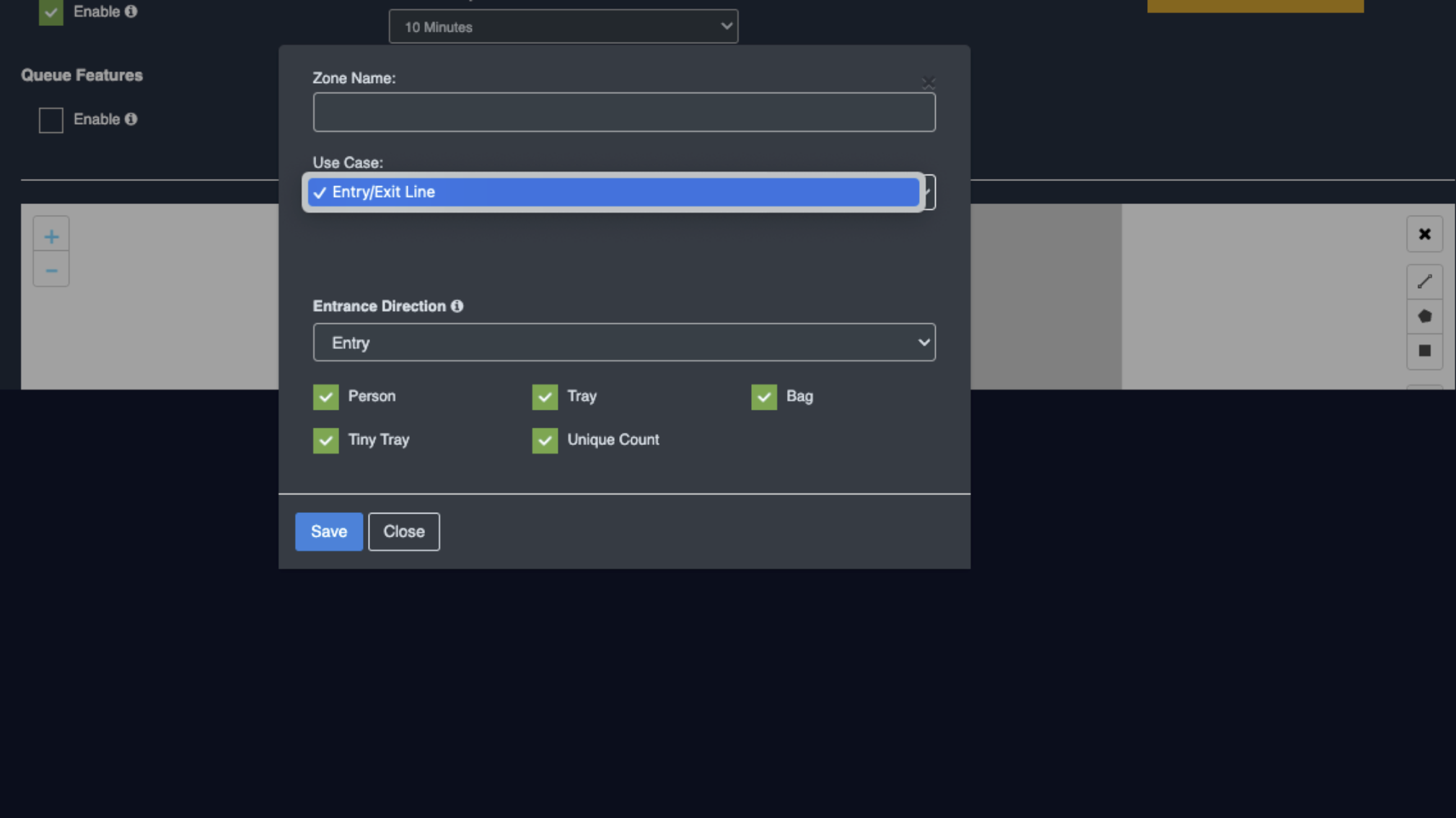
Enter the zone name in the popup window that opens, select the features you want to detect while entry or exit.
After selecting click the Save button.
New ROI zone added successfully
Draw ROI using the Polygon tool.
Click on the Polygon tool button from the camera frame.
Then connect the dots and draw the polygon in the space where you want to draw the ROI. It should have more than 2 points.
After drawing, click the Finish button to complete the drawing.
Enter the zone name in the popup window that opens and click the Save button.
New ROI zone added successfully.
Draw ROI using the rectangle tool.
Click on the Rectangle tool button from the camera frame.
Then draw the rectangle where you want to focus the camera.
13. Then enter the zone name and select Restrict to selected area of interest option from the dropdown list and click the Save button.
Detection will only happen when people enter this zone.
With this ROI you can achieve the below Features:
Countable Objects
Once the Use case Configuration is done, click on save.
Your Camera is configured for Entry/Exit.
Update/ sync Configuration:
Once you perform any change in the controller or update any features/ use cases for camera you need to sync it.
There are 2 types of syncing process:
Sync the configurations
Update the Configurations
Click on sync configuration to restart the complete system syncing process. Basically for the initial camera setup and while any controller configuration update. (It will restart the docker and sync all the performed changes)
Click on the update configuration to recent changes in the system without any downtime. (General configuration sync)
Retail Leakage(RLCC)
Before you begin configuring the use cases, you should first configure the camera’s general configuration. Refer to the General Camera Configuration section for instructions.
Then, select the Retail Leakage from the dropdown list
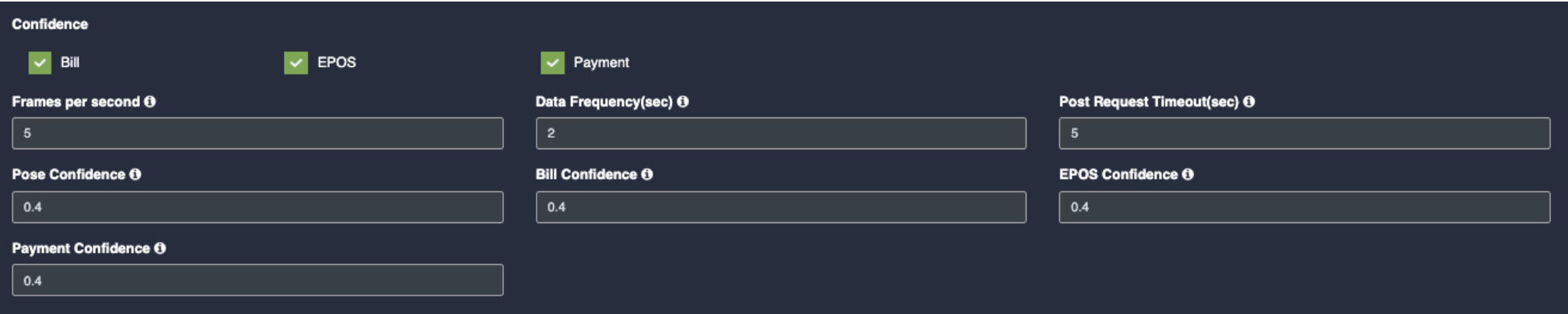
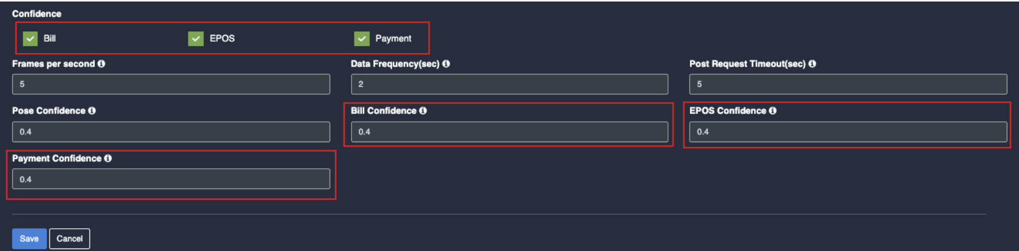
Scroll down and choose your preferred use cases. You can choose multiple Features.
Confidence: (certainty that a detected object, person or action is correctly identified)
Bill: Once you click on the check box of Bill, their respective dropdowns will be added below for the respective feature detection.
EPOS: Once you click on the check box of EPOS, their respective dropdowns will be added below for the respective feature detection.
Payment: Once you click on the check box of payment, their respective dropdowns will be added below for the respective feature detection.
Draw ROI (region of interest) on the camera frame.
ROI in camera frames can help to improve efficiency, accuracy, and reduce storage requirements.
ROI must be added if kiosk mode is enabled. Otherwise, it is optional. If ROI is not added, the model will detect the entire frame.
For face detection, ROI can be drawn in two ways.
Using the polygon tool
Using the rectangle tool.
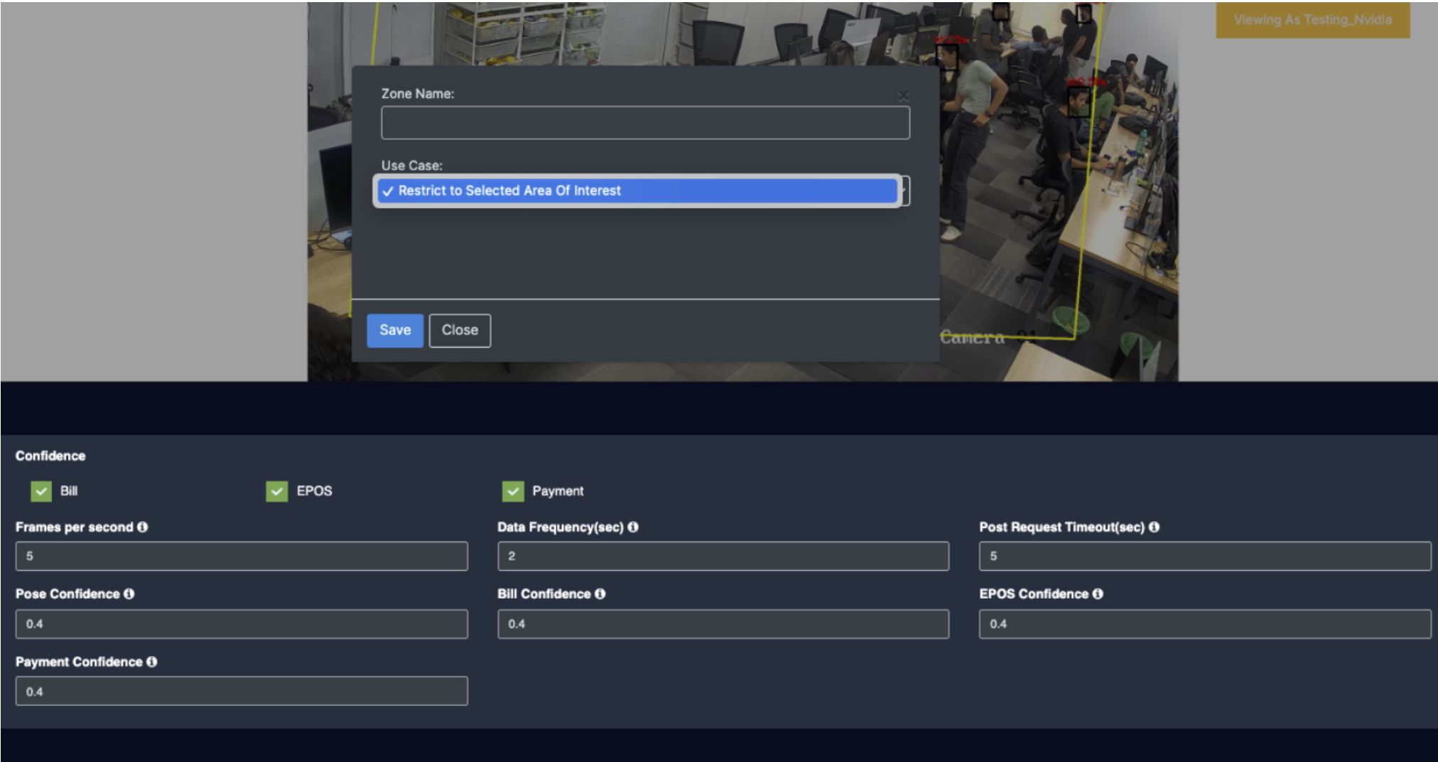
Draw ROI using the Polygon tool.
Click on the Polygon tool button from the camera frame.
Then connect the dots and draw the polygon in the space where you want to draw the ROI. It should have more than 2 points.
After drawing, click the Finish button to complete the drawing.
Enter the zone name in the popup window that opens and click the Save button.
New ROI zone added successfully.
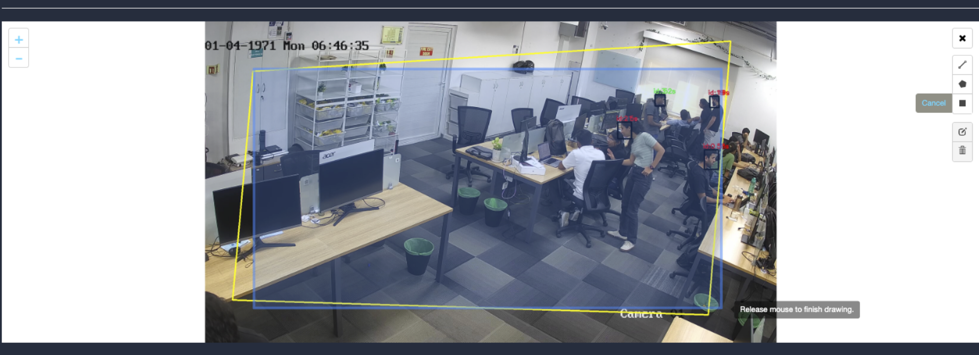
Draw ROI using the rectangle tool.
Click on the Rectangle tool button from the camera frame.
Then draw the rectangle where you want to focus the camera.
Then enter the zone name and select Restrict to selected area of interest option from the dropdown list and click the Save button.
Detection will only happen when people enter this zone.
With this ROI you can achieve the below Features:
All Confidence features
Once the Use case Configuration is done, click on save.
Your Camera is configured for RLCC.
Update/ sync Configuration:
Once you perform any change in the controller or update any features/ use cases for camera you need to sync it.
There are 2 types of syncing process:
Sync the configurations
Update the Configurations
Click on sync configuration to restart the complete system syncing process. Basically for the initial camera setup and while any controller configuration update. (It will restart the docker and sync all the performed changes)
4. Click on the update configuration to recent changes in the system without any downtime. (General configuration sync)
Vehicle Monitoring
Before you begin configuring the use cases, you should first configure the camera’s general configuration. Refer to the General Camera Configuration section for instructions.
Then, select the Vehicle monitoring from the dropdown list
3. Scroll down and choose your preferred use cases. You can choose multiple Features.
4. In Vehicle Monitoring there are 2 types of detection
Vehicle Entry/Exit
Vehicle Tracking
Vehicle Entry/Exit have 2 type of tracking features, which is Vehicle and License Plate.
6. Selecting any of the type will show the respective check boxes and dropdown below.
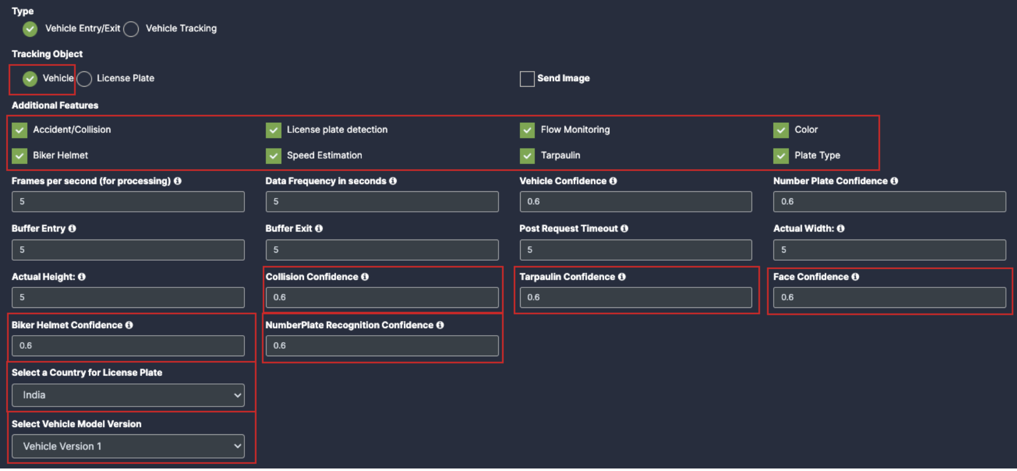
7. Selecting Vehicle:
Accident/Collision: Once you click on the check box of Accident/Collision, their respective dropdowns will be added below for the respective feature detection.
License plate detection: Once you click on the check box of License plate detection, their respective dropdowns and Plate type check box will be added below for the respective feature detection.
Flow Monitoring: Once you click on the check box of Flow Monitoring, their respective dropdowns will be added below for the respective feature detection.
Color: Once you click on the check box of Color, their respective dropdowns will be added below for the respective feature detection.
Biker Helmet: Once you click on the check box of Biker Helmet, their respective dropdowns will be added below for the respective feature detection.
Speed Estimation: Once you click on the check box of Speed Estimation, their respective dropdowns will be added below for the respective feature detection.
Tarpaulin: Once you click on the check box of Tarpaulin, their respective dropdowns will be added below for the respective feature detection.
Plate type: Enable the check box of plate type for respective detection.
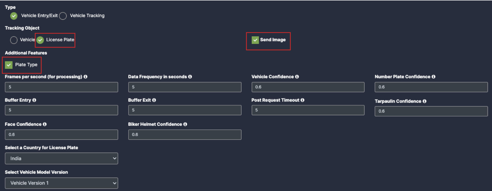
8. Selecting License Plate:
Plate Type: To detect the License Plate and its Type.
Accident/Collision: Once you click on the check box of Accident/Collision, their respective dropdowns will be added below for the respective feature detection.
License plate detection: Once you click on the check box of License plate detection, their respective dropdowns will be added below for the respective feature detection.
Flow Monitoring: Once you click on the check box of Flow Monitoring, their respective dropdowns will be added below for the respective feature detection.
Color: Once you click on the check box of Color, their respective dropdowns will be added below for the respective feature detection.
Biker Helmet: Once you click on the check box of Biker Helmet, their respective dropdowns will be added below for the respective feature detection.
Speed Estimation: Once you click on the check box of Speed Estimation, their respective dropdowns will be added below for the respective feature detection.
Tarpaulin: Once you click on the check box of Tarpaulin, their respective dropdowns will be added below for the respective feature detection.
Plate Type: Enable the check box of plate type for the respective detection.
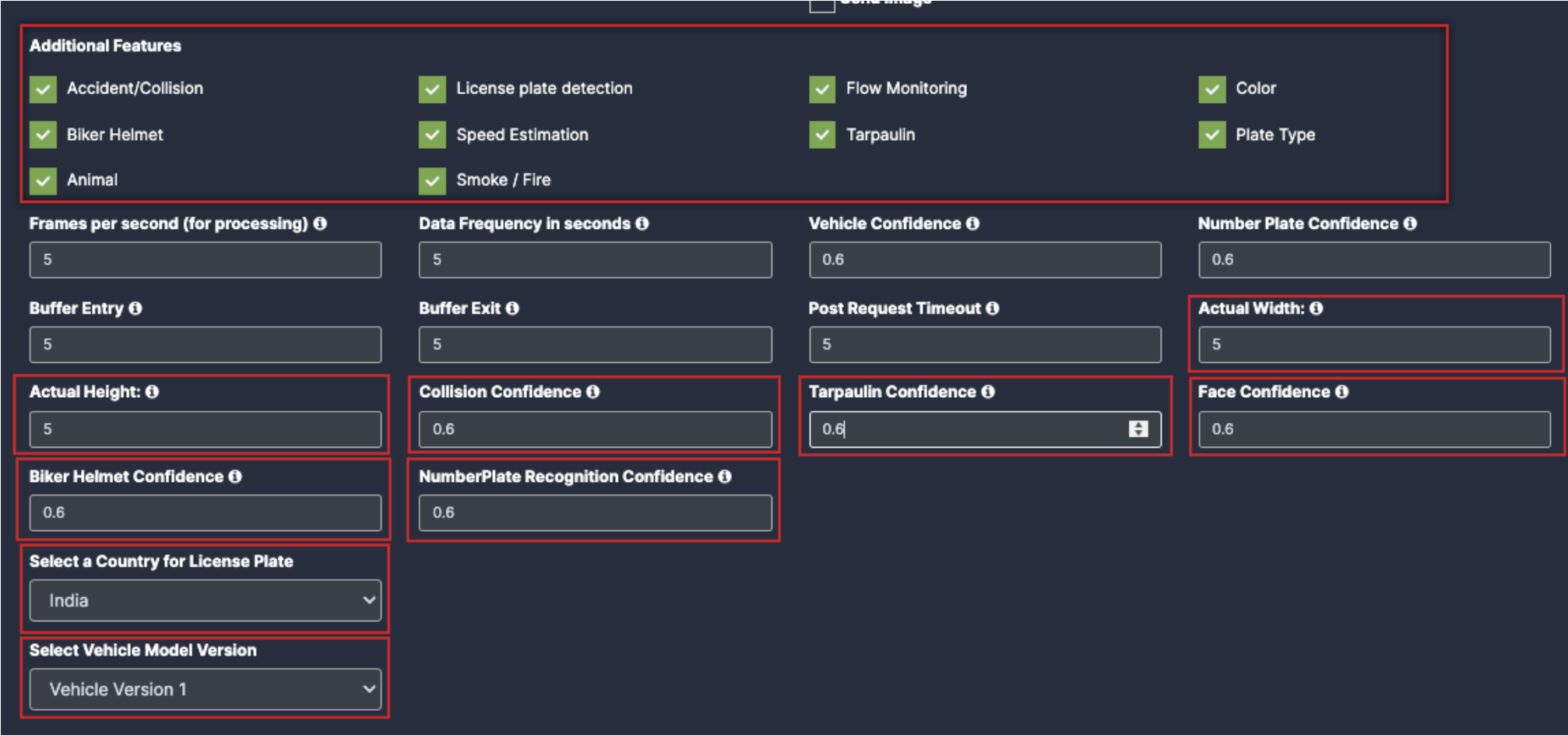
Animal: Enable the check box of Animal for the respective detection
Smoke/Fire: Enable the check box of Smoke/Fire for the respective detection.
Draw ROI (region of interest) on the camera frame.
ROI in camera frames can help to improve efficiency, accuracy, and reduce storage requirements.
ROI must be added if kiosk mode is enabled. Otherwise, it is optional. If ROI is not added, the model will detect the entire frame.
For face detection, ROI can be drawn in two ways.
Using the polygon tool
Using the rectangle tool.
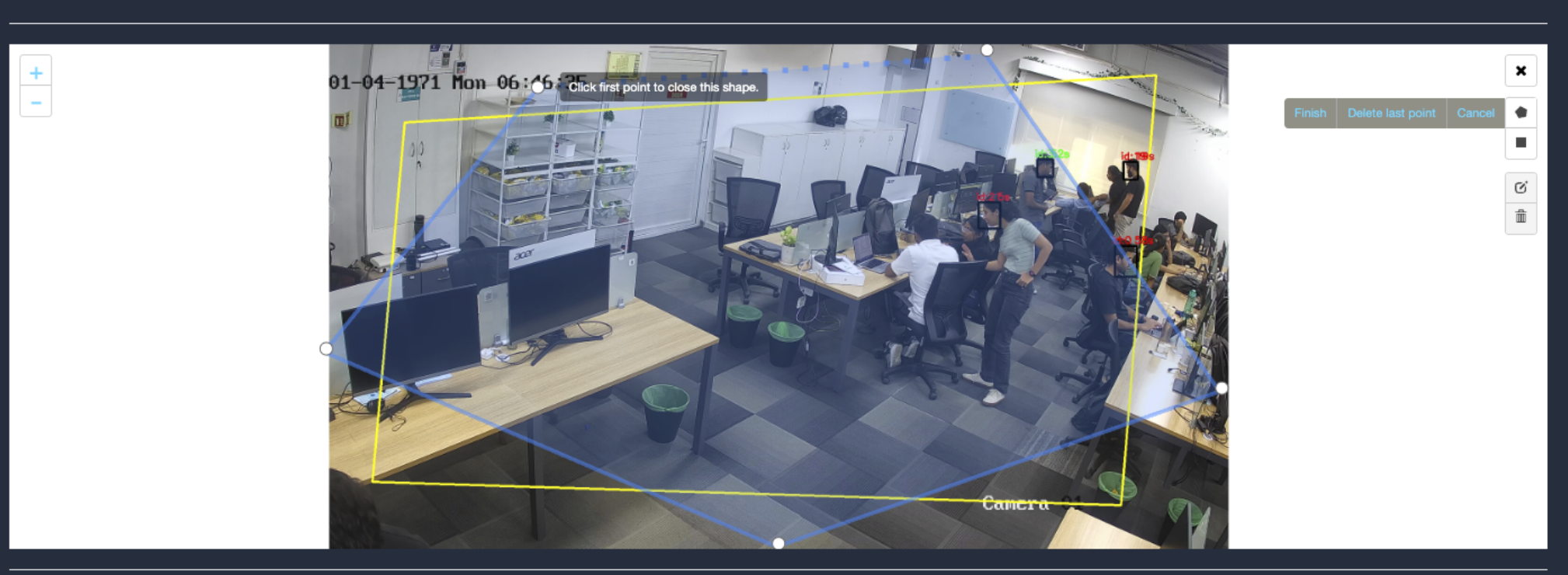
Draw ROI using the Polygon tool.
Click on the Polygon tool button from the camera frame.
Then connect the dots and draw the polygon in the space where you want to draw the ROI. It should have more than 2 points.
12. After drawing, click the Finish button to complete the drawing.
11. Enter the zone name in the popup window that opens and click the Save button.
12. New ROI zone added successfully.
Draw ROI using the rectangle tool.
Click on the Rectangle tool button from the camera frame.
Then draw the rectangle where you want to focus the camera.
23. Then enter the zone name and select Restrict to selected area of interest option from the dropdown list and click the Save button.
24. Detection will only happen when people enter this zone.
25. With this ROI you can achieve the below Features:
All Vehicle Detection
Tracking Object
Additional Features
Once the Use case Configuration is done, click on save.
Your Camera is configured for Vehicle Monitoring.
Update/ sync Configuration:
Once you perform any change in the controller or update any features/ use cases for camera you need to sync it.
There are 2 types of syncing process:
Sync the configurations
Update the Configurations
3. Click on sync configuration to restart the complete system syncing process. Basically for the initial camera setup and while any controller configuration update. (It will restart the docker and sync all the performed changes)
Click on the update configuration to recent changes in the system without any downtime. (General configuration sync)
Airside Operations
Before you begin configuring the use cases, you should first configure the camera’s general configuration. Refer to the General Camera Configuration section for instructions.
Then, select the Airside operations from the dropdown list
Scroll down and you will see the 2 type of detection which is:
Air Trafficator
TAT(Turnaround Time)
Select Air trafficator, scroll down and choose your preferred use cases. You can choose multiple Features.
5. Features:
Aircraft: Once you enable the checkbox of Aircraft, you will get respective confidence and version dropdown.
Traffic Lights: Once you enable the checkbox of Traffic Lights, you will get respective confidence and version dropdown.
Vehicle: Once you enable the checkbox of Vehicle, you will get respective confidence and version dropdown.
6. Safety:
Birds: Once you enable the checkbox of Birds, you will get respective confidence.
FOD: Once you enable the checkbox of FOD, you will get respective confidence.
People: Once you enable the checkbox of People, you will get respective confidence.
Safety Jacket: Once you enable the checkbox of Safety Jacket, you will get respective confidence.
Spillage: Once you enable the checkbox of Spillage, you will get respective confidence.
7. Settings:
Data Frequency(sec): Fill the setting as per your requirements
Frames/Sec: Fill the setting as per your requirements
Post Request Timeout(sec): Fill the setting as per your requirements
Now, Select TAT and scroll down to choose your preferred use cases. You can choose multiple Features.
In TAT there is view type which contains 4 options:
Nose: The Camera capture the frontal view of the aircraft, primarily focusing on the nose section.
BFL(Baggage freight loader): The camera provides the clear view of the aircraft’s left side, capturing operations and equipment positioned on this side.
TOP: The Camera is mounted overhead to provide a bird’s-eye view of the aircraft and its surroundings. This offers comprehensive coverage of all ground activities around the aircraft.
Right: This perspective covers the right side of the aircraft, suitable for monitoring activities or equipment on that side.
Selecting each of the view type will provide the respective checkboxes below:
11. Select view type: Nose
Model Version: Select the model version as per your requirement.
Select view type: BFL(Baggage freight loader)
Aircraft: Once you enable the checkbox of Aircraft, you will get respective confidence to fill
Baggage Loader: Once you enable the checkbox of Baggage Loader, you will get respective confidence to fill
Baggage Truck: Once you enable the checkbox of Baggage Truck, you will get respective confidence to fill
Bags: Once you enable the checkbox of Bags, you will get respective confidence to fill
Cargo Door: Once you enable the checkbox of Cargo Door, you will get respective confidence to fill
Catering Truck: Once you enable the checkbox of Catering Truck, you will get respective confidence to fill
Fuel Truck: Once you enable the checkbox of Fuel Truck, you will get respective confidence to fill
GPU(Ground Power Unit): Once you enable the checkbox of GPU, you will get respective confidence to fill
PCA(Pre conditioned air): Once you enable the checkbox of PCA, you will get respective confidence to fill
Push Back Vehicle: Once you enable the checkbox of Push Back Vehicle, you will get respective confidence to fill
Push Back Tug: Once you enable the checkbox of Push Back Tug, you will get respective confidence to fill
Select view type: TOP
Aircraft: Once you enable the checkbox of Aircraft, you will get respective confidence to fill
Baggage Loader: Once you enable the checkbox of Baggage Loader, you will get respective confidence to fill
Baggage Truck: Once you enable the checkbox of Baggage Truck, you will get respective confidence to fill
Bags: Once you enable the checkbox of Bags, you will get respective confidence to fill
Cargo Door: Once you enable the checkbox of Cargo Door, you will get respective confidence to fill
Catering Truck: Once you enable the checkbox of Catering Truck, you will get respective confidence to fill
Chocks: Once you enable the checkbox of Chocks, you will get respective confidence to fill
Fuel Truck: Once you enable the checkbox of Fuel Truck, you will get respective confidence to fill
Generator: Once you enable the checkbox of Generator, you will get respective confidence to fill
GPU(Ground Power Unit): Once you enable the checkbox of GPU, you will get respective confidence to fill
GT Bus: Once you enable the checkbox of GT Bus, you will get respective confidence to fill
GT Tractor: Once you enable the checkbox of GT Tractor, you will get respective confidence to fill
GT TRUCK: Once you enable the checkbox of GT TRUCK, you will get respective confidence to fill
PBB(passenger boarding bridge): Once you enable the checkbox of PBB, you will get respective confidence to fill
PCA(Pre conditioned air): Once you enable the checkbox of PCA, you will get respective confidence to fill
Push Back Vehicle: Once you enable the checkbox of Push Back Vehicle, you will get respective confidence to fill
Push Back Tug: Once you enable the checkbox of Push Back Tug, you will get respective confidence to fill
Staircase: Once you enable the checkbox of Staircase, you will get respective confidence to fill
14. Select view type: Right
Aircraft: Once you enable the checkbox of Aircraft, you will get respective confidence to fill
Catering Truck: Once you enable the checkbox of Catering Truck, you will get respective confidence to fill
Chocks: Once you enable the checkbox of Chocks, you will get respective confidence to fill
GPU(Ground Power Unit): Once you enable the checkbox of GPU, you will get respective confidence to fill
PBB(passenger boarding bridge): Once you enable the checkbox of PBB, you will get respective confidence to fill
PCA(Pre conditioned air): Once you enable the checkbox of PCA, you will get respective confidence to fill
Push Back Vehicle: Once you enable the checkbox of Push Back Vehicle, you will get respective confidence to fill
Push Back Tug: Once you enable the checkbox of Push Back Tug, you will get respective confidence to fill
Staircase: Once you enable the checkbox of Staircase, you will get respective confidence to fill
15. Safety(common:
Birds: Once you enable the checkbox of Birds, you will get respective confidence.
FOD: Once you enable the checkbox of FOD, you will get respective confidence.
People: Once you enable the checkbox of People, you will get respective confidence.
Safety Jacket: Once you enable the checkbox of Safety Jacket, you will get respective confidence.
Spillage: Once you enable the checkbox of Spillage, you will get respective confidence.
Setting:
Data Frequency(sec): Fill the setting as per your requirements
Frames/Sec: Fill the setting as per your requirements
Post Request Timeout(sec): Fill the setting as per your requirements
Draw ROI (region of interest) on the camera frame.
ROI in camera frames can help to improve efficiency, accuracy, and reduce storage requirements.
ROI must be added if kiosk mode is enabled. Otherwise, it is optional. If ROI is not added, the model will detect the entire frame.
For face detection, ROI can be drawn in two ways.
Using the polygon tool
cUsing the rectangle tool.
Draw ROI using the Polygon tool (Air Trafficator)
Click on the Polygon tool button from the camera frame.
Then connect the dots and draw the polygon in the space where you want to draw the ROI. It should have more than 2 points.
15. After drawing, click the Finish button to complete the drawing.
Enter the zone name in the popup window that opens and click the Save button.
New ROI zone added successfully.
Draw ROI using the rectangle tool(Air Trafficator)
Click on the Rectangle tool button from the camera frame.
Then draw the rectangle where you want to focus the camera.
Then enter the zone name and select Restrict to selected area of interest option from the dropdown list and click the Save button.
Detection will only happen when people enter this zone.
With this ROI you can achieve the below Features:
Countable Objects
Once the Use case Configuration is done, click on save.
TAT:
Draw ROI using the Polygon tool (TAT: Nose view type)
Click on the Polygon tool button from the camera frame.
Then connect the dots and draw the polygon in the space where you want to draw the ROI. It should have more than 2 points.
18. After drawing, click the Finish button to complete the drawing.
15. Enter the zone name in the popup window that opens and click the Save button.
16. New ROI zone added successfully.
Draw ROI using the rectangle tool(TAT: Nose view type)
Click on the Rectangle tool button from the camera frame.
Then draw the rectangle where you want to focus the camera.
32. Then enter the zone name and select Restrict to selected area of interest option from the dropdown list and click the Save button.
Detection will only happen when people enter this zone.
Once the Use case Configuration is done, click on save.
BFL view type:
Draw ROI using the Polygon tool (TAT: BFL view type)
Click on the Polygon tool button from the camera frame.
Then connect the dots and draw the polygon in the space where you want to draw the ROI. It should have more than 2 points.
21. After drawing, click the Finish button to complete the drawing.
17. Enter the zone name in the popup window that opens and click the Save button.
18. New ROI zone added successfully.
Draw ROI using the rectangle tool(TAT: BFL view type)
Click on the Rectangle tool button from the camera frame.
Then draw the rectangle where you want to focus the camera.
Then enter the zone name and select Restrict to selected area of interest option from the dropdown list and click the Save button.
36. Detection will only happen when people enter this zone.
37. Once the Use case Configuration is done, click on save.
TOP view type:
Draw ROI using the Polygon tool (TAT: Top view type)
Click on the Polygon tool button from the camera frame.
Then connect the dots and draw the polygon in the space where you want to draw the ROI. It should have more than 2 points.
After drawing, click the Finish button to complete the drawing.
19. Enter the zone name in the popup window that opens and click the Save button.
20. New ROI zone added successfully.
Draw ROI using the rectangle tool(TAT: Top view type)
Click on the Rectangle tool button from the camera frame.
Then draw the rectangle where you want to focus the camera.
Then enter the zone name and select Restrict to selected area of interest option from the dropdown list and click the Save button.
39. Detection will only happen when people enter this zone.
40. Once the Use case Configuration is done, click on save.
Right view type:
Draw ROI using the Polygon tool (TAT: Right view type)
Click on the Polygon tool button from the camera frame.
Then connect the dots and draw the polygon in the space where you want to draw the ROI. It should have more than 2 points.
27. After drawing, click the Finish button to complete the drawing.
21. Enter the zone name in the popup window that opens and click the Save button.
22. New ROI zone added successfully.
Draw ROI using the rectangle tool(TAT: Right view type)
Click on the Rectangle tool button from the camera frame.
Then draw the rectangle where you want to focus the camera.
Then enter the zone name and select Restrict to selected area of interest option from the dropdown list and click the Save button.
42. Detection will only happen when people enter this zone.
43. Once the Use case Configuration is done, click on save.
44. Your Camera is configured for Airside Monitoring.
Update/ sync Configuration:
Once you perform any change in the controller or update any features/ use cases for camera you need to sync it.
There are 2 types of syncing process:
Sync the configurations
Update the Configurations
Click on sync configuration to restart the complete system syncing process. Basically for the initial camera setup and while any controller configuration update. (It will restart the docker and sync all the performed changes)
Click on the update configuration to recent changes in the system without any downtime. (General configuration sync)
Integrating with KloudInsights
Same as before:
Creating Rules and Notifications
Same as before:
Generating Widgets and Insights
Same as before:
Video Gallery and Playback
Same as before:
Queue Creation
Go to “Queue configuration” to access the queue management settings.
Click on “Create queue configuration” to initiate the setup process.
In the opening window, enter the name of the queue.
Click the “Create” button to proceed.
In the “Configure Queue System” window, you’ll find the Lane, Server, and Gate buttons on the right-hand side.
Add Lanes:
Double-click on the “Lane” button.
In the popup window, specify the number of lanes.
Click “Add” to add the lanes to the canvas.
4. Adjust the lane positions according to your requirements by dragging them.
Add Tag:
You can right the reference location or any unique name as tag.
Add Servers:
Double-click on the “Server” button.
In the popup window, select the number of servers.
Click “Add” to add server gates to the canvas.
Adjust the server gate positions as needed.
Add Exit Gates:
Double-click on the “Gate” button to add exit gates.
In the popup window, specify the number of exit gates.
Click “Add” to add exit gates to the canvas.
4. Adjust the exit gate positions according to your needs.
Draw Association Lines:
Click on the icon representing the association you want to create.
The selected icon’s color will change to yellow.
3. Click on the associated icon to create an association line between them.
4. Repeat the process to create associations between other icons.
Save Configuration:
Click the “Save Configuration” button to save the configured queue.
Delete Associations:
To delete an association, click on the “Delete association” button.
Select the association lane to be deleted.
A confirmation window will appear; click “Yes, I do” to confirm the deletion process.
4. Finally, click on the Save Configuration button to save the changes.
Management, Monitoring of KloudController
When monitoring is enabled for NVIDIA KloudController, it allows us to receive email notifications whenever the controller goes down. This is crucial for maintaining system reliability and ensuring timely intervention.
It is important to enable to this Alerts to Monitor the controller
Monitoring KloudController and Cameras
We can monitor the KloudController Active or In Active Status in the Kloud Manage Application by configuring the Alerts
To configure Alerts first we need to create contact in Settings > Contacts> Click on +Contact
Provide the required information and select Type as Email
Before configuring the Alerts, please ensure that *** Email Setup is done in Settings> Third party settings***
To Enable Alerts, Navigate to Settings > Alert Notifications
Click Add Alert Notification Button and configure alerts accordingly
Monitor and Manage KloudController Services
We Can Manage, Monitor and Troubleshoot KloudController from Kloud Manage
Navigate to Kloud Controller Tab
Select on the appropriate controller to monitor and manage it
Clicking on the controller’s name will fetch real-time information from the controller.
System Information
Status: Shows whether the controller is operational.
Device Power Red-> Power is down Green -> Power is UP
API Connection Red-> API Not Connected Green -> API Connected
(Note: If the API connection fails, there is no need to worry as data transfer is happening through WebSocket.)
WebSocket Connection Red-> WebSocket Not Connected
Green -> WebSocket Connected
Uptime: Displays the duration for which the device has been running.
Model & Version: Identifies the hardware and software version of the Kloud Controller
NTP Server
NTP Server: This section displays the NTP server details. If the controller is not Synced to an NTP server, the section will remain empty. An NTP server can be added or modified using the Edit button.
Once the NTP server is added we can verify the system clock synchronized status and service status as above
Network Status
IP Address: Shows the assigned IP (e.g., 192.168.1.2).
Connectivity Status: Indicates if the device is Connected, Reachable, and Enabled.
Services
This section displays the status of services, including whether they are Running, Not Running, Up, or Down, along with the associated Docker image name.
In the Action column, there are three buttons to:
Edit the image name.
Restart a service.
Start/Stop a service.
Clicking the Edit button opens a page where you can modify the image name and save the changes (We recommend checking latest image id with kloudspot Team) .
Resource Utilization
Memory Usage: Displays total available and used memory.
GPU Utilization: Shows GPU load distribution across different processing tasks.
CPU Temperature: Graphs per-core temperature readings.
Disk Information
This section provides details about the storage devices, including mount points, total storage, used space, available space, and percentage usage.
Device Platform Details
Displays essential system information such as:
Operating System Name
Node (Hostname)
OS Release Version
Kernel Version
Machine Architecture (e.g., x86_64)
Processor Details
CPU Usage
A graphical representation of CPU utilization across different cores, helping in monitoring system performance.
Common Troubleshooting Scenarios
Troubleshooting scenarios can be performed by logging into TTY (Terminal).
(Please ensure a display is connected to the controller if it is not already attached.)
Steps to Access TTY:
Press ALT + Ctrl + F5 to switch to TTY5.
Enter the following credentials
Username: kloudspotPassword: kloudspot123
After successful we will be able to see below options
Installation Issues:
For troubleshooting Installation Issues please refer to 5.3 Troubleshooting Installation Issues
Network Connectivity:
What should we do if KloudController cannot connect to the internet?
Log in to the KloudController.
Check the IP address of the controller to verify whether the desired IP address has been assigned.
To verify the IP Address, refer to 5.4.1 Setting up Network Configurations
If the IP address is not assigned:
  Check the network connectivity to ensure the controller is properly connected.

  Verify DHCP settings if using automatic IP assignment.

  If a static IP needs to be configured, refer to the 5.4.1 Setting up Network Configurations for detailed steps
Once the IP is assigned, proceed with the following diagnostic steps:
Choose option 6 to perform Network Diagnostics
From the Network Diagnostics menu, choose Option 1 to run a ping test and check connectivity.
If the ping test fails, choose Option 2 to run a traceroute and diagnose network path issues.
If connectivity issues persist:
  Check the internet connection to the controller.

  Reboot the controller and repeat the steps above.
Are there specific diagnostics we should perform (e.g., checking DNS or NTP settings)?
Users can also check and modify the current Network configuration by choosing option 5 in main menu
Verify Current Network Settings:
  Choose Option 1 to check details such as:
  - Network Interface
  - Mode
  - IP Address
  - Gateway
  - DNS Server
*For Security reasons few IP Address are hidden in above screenshot
Select Option 2 to set up a new network configuration if needed.
TO check NTP server settings refer to NTP COnfigurations
What should we do if KloudController cannot connect to the Kloudspot Platform?
Select Option 7 to display the device status from the main menu
Registration Status – If the device is licensed, the status will be True; otherwise, it will be False.
WebSocket Connection – If the device is successfully connected to the application server, the status will be True; otherwise, it will be False.
If both Registration Status and Web Socket Connection is False, please contact Kloudspot Support Team to provide required Licence
TCP Connection Status – This is used for maintenance and software upgrades by the Kloudspot team. By default, the status is Disconnected. but it will be enabled when a Kloudspot engineer is working on the device.
What should we do if KloudController is not showing camera feed?
Choose Option 1 to check Kloudspot service status from the main menu
If services are updating, allow the controller to complete the update Successfully.
If the required services are not running, go back and choose Option 2 to download and restart the services.
Service Failures:
What is some typical service-related problems (e.g., KloudVision failing to connect to a camera)?
If KloudVision or another service fails to connect to a camera, check the following:
RTSP Port Blocked:
Ensure RTSP port 554 is enabled in the firewall or network settings.
If using a custom RTSP port, verify the correct port is configured.
Incorrect Camera Credentials:
Verify the username and password in the RTSP URL match the camera’s login credentials.
Check for any case-sensitive mismatches.
Test Raw Camera Feed:
Open VLC Media Player and try streaming the RTSP feed directly.
If the stream fails, the issue may be with the camera settings or network.
Camera Network & Configuration:
Ensure the camera is powered on and connected to the network.
Check if the camera IP address is correct and accessible.
Verify that the camera firmware is up to date.
Are there logs or tools users can check for troubleshooting these services?
  * Users can check various logs using Option 14, which provides valuable insights into system behaviour and potential issues. Below is an overview of what each log contains:

  * If you need to exit from any logs press ctrl+c

  1. System Logs:

          a. Includes general system activity, errors, and events.
          b. Useful for diagnosing service failures, crashes, and hardware issues.
          c. Helps identify boot issues, network failures, or unexpected reboots.


  2. Drop spot Logs:
          a. Specific to Kloudspot services and Dropspot operations.
          b. Logs device registration, connectivity, and service interactions.
          c. Useful for diagnosing platform-related issues, such as data not syncing with Kloudspot.

  3. Kernel Logs:
          a. Contains low-level system events related to the Linux kernel.
          b. Logs hardware interactions, driver errors, and system stability issues.
          c. Useful for troubleshooting hardware failures, crashes, or performance bottlenecks.
Performance Issues:
What should users check if a service is running slower than expected (e.g., camera feeds in KloudVision lagging)?
If a service is running slower than expected, users should check the following:
Network Bandwidth & Latency:
a. Perform a ping test (Option 1 in Network Diagnostics) to check latency.
Device Resource Utilization:
 a.Check CPU and memory usage on the device to ensure it is not overloaded.
 b. Restart the device if resource usage is consistently high.
Camera-Specific Checks (For KloudVision):
a. Ensure the camera’s network connection is stable.
b. Verify that the camera stream settings (resolution, frame rate) are optimized for the network conditions.
c. Restart the camera and check for firmware updates.
Service Status & Logs:
 a. Use Option 1 to check the service status and ensure all necessary services are running.
 b. Check logs for any error messages that indicate performance issues.
 c. If the issue persists, try Download update and restart services using Option 2.
Any recommendations for optimizing performance (e.g., adjusting hardware resources)?
To improve performance and reduce lag in services like KloudVision, consider the following optimizations:
Network Optimization:
 a. Ensure a stable and high-speed internet connection with sufficient bandwidth for video streaming.
 b. Prioritize network traffic using QoS (Quality of Service) settings on your router.
 c. Reduce network congestion by limiting other high-bandwidth activities.
Hardware Resource Adjustments:
 a. Increase CPU & RAM allocation if the device is under heavy load.
 b. Use an SSD instead of an HDD for faster data processing.
 c. Ensure proper cooling to prevent performance throttling due to overheating.
Camera & Video Settings (For KloudVision):
 a. Adjust resolution and frame rate based on available bandwidth and processing power.
 b. Enable motion-based recording instead of continuous streaming to save resources.
 c. Keep camera firmware updated for performance improvements.
How Does NTP Configuration Affect Cameras and Connectivity to the Application Server?
Why is NTP (Network Time Protocol) important for system performance?
Proper time synchronization ensures accurate event logging, reduces
connectivity issues with the application server and prevents delays in camera feeds.
How can users configure NTP settings?
Select Option 8 to configure NTP settings.
Set the correct NTP server to synchronize time with a reliable source.
Restart services if necessary to apply changes.
What issues can occur if NTP is misconfigured?
Camera feeds may experience lag due to time drift.
Connectivity to the application server may be unstable if timestamps mismatch.
Event logs may have incorrect timestamps, making troubleshooting difficult.
FAQ
General Questions:
What happens if the hardware specs are below the recommended requirements?
Running KloudController on lower specs may result in performance issues such as slower processing, reduced camera feed quality, or application crashes. It is recommended to upgrade the hardware to meet the minimum specifications for Optimal performance.
Can multiple users access KloudController simultaneously?
Yes, KloudController supports multi-user access
Can I access KloudController remotely when I’m not on the same network?
Yes, you can access KloudController remotely if remote access is configured through VPN, port forwarding, or cloud integration.
What should I do if I accidentally misconfigure the network settings?
You can reset the network settings by accessing the controller via a connected display and using the “Set/Edit Network Configuration” option.
Does KloudController store any of my personal data or logs? KloudController only stores system logs and service-related data for diagnostics. No personal data is collected
What happens if KloudController runs out of storage space? If storage is full, certain logs and non-critical data will be overwritten. It is recommended to monitor disk usage and expand storage if needed For monitoring Disk Usage Refer to 9.2.5 Disk Information
Service-Specific Questions:
KloudVision:
1.What types of cameras are supported?
KloudVision supports RTSP-compatible IP cameras, ONVIF cameras, and select USB cameras.
2.How many cameras can be configured to one KloudController?
The number of supported cameras depends on hardware specifications for more details refer to Hardware recomendation section
3.Can I access camera feeds remotely?
Yes, camera feeds can be accessed remotely if configured with proper security settings.
4.What should I do if my camera feed is not showing?
Ensure the camera is powered on, correctly connected to the network, and that the RTSP URL is correctly configured. Check weather services are running/Stopped
Make sure that you have Enabled below:
Enable HTTPS
Show Processing information on video feed
5. How does KloudVision’s face detection feature work?
KloudVision’s face detection feature identifies individuals who enter a premises, monitors their movements, and tracks their behaviour using AI and computer vision. It’s valuable for enhancing security and managing access in high- Security areas.
Support:
Where can I find Kloudspot’s documentation and user manuals?
All manuals, guides, and API documentation are available on the Kloudspot Documentation Portal.
How can I contact Kloudspot Support?
You can reach Kloudspot Support through Email: support@kloudspot.com
Integrating with KloudInsights
Once the camera has been configured, the subsequent step is to integrate KloudVision with the KloudInsights platform.
Integrating KloudVision with the KloudInsights platform provides the capability to analyze the data collected by KloudVision cameras and create a wide range of widgets based on it.
Kloudinsights software allows users to set up rules to monitor different
events or conditions. These rules are designed to automatically trigger
actions or notifications whenever certain conditions are met.
To create a rule in Kloudinsights, the user must define the condition that
needs to be monitored. The user can choose from a variety of predefined
conditions such as Gender detection, mask detection, helmet detection, medical
glows detection, and so on.
After the rule is created, it is automatically triggered whenever the
specified condition is met. For example, if the user sets a rule to monitor
instances where an individual enters an area without wearing a mask, the rule
will trigger a notification if someone enters the location without a mask.
Create rule
Refer to the KloudInsights “Creating Rules
" section to learn how to create a rule. Alternatively, you can use the “Action Templates” section if you want to create an action template.
Use “Add Vision Entity Conditions” button to create vision rules.
Generating Widgets and Insights
1. KloudVision is a technology that enables businesses to gather and analyze data about customer behavior in physical spaces such as retail stores, malls, and event venues. With the information obtained from KloudVision, businesses can create various types of widgets that provide valuable insights into their customers’ behavior and demographics.
2. Refer Creating dashboards section to know how to create related widgets with KloudVision. This is possible by connecting KloudVision with KloudInsights. Refer Integrating with KloudInsights section to know how to connect KloudVision with kloudInsights.
3. Refer to the Dashboards section to know which widgets are available in KloudVision.
Video Gallery and Playback
There are two methods to view video surveillance footage (video snippets).
Method 1:
Click on the Camera Surveillance menu. Then select your desired office location in the map view that opens.
Immediately a window containing the footage will open, from which you can search for the footage you want.
Here we are supporting Natural Language Search of videos. For example: If you want to search for a person wearing a black shirt, search for “person with Back shirt” in the search bar and you will get videos of a person wearing a black shirt.
Method 2:
Navigate to Camera Surveillance > Video gallery and select the location from the Select Venue dropdown list.
Immediately a window containing the footage will open, from which you can search for the footage you want.
Queue creation
To configure queue monitoring on a camera, the initial step involves creating a queue. A complete queue configuration should encompass a lane, server, and gate.
The exact copy of the queue you want to configure needs to be created here.
Navigate to the Vision Controller interface.
Go to “Queue configuration” to access the queue management settings.
Click on “Create queue configuration” to initiate the setup process.
In the opening window, enter the name of the queue.
Click the “Create” button to proceed.
In the “Configure Queue System” window, you’ll find the Lane, Server, and Gate buttons on the right-hand side.
Add Lanes:
Double-click on the “Lane” button.
In the popup window, specify the number of lanes.
Click “Add” to add the lanes to the canvas.
Adjust the lane positions according to your requirements by dragging them.
Add Servers:
Double-click on the “Server” button.
In the popup window, select the number of servers.
Click “Add” to add server gates to the canvas.
Adjust the server gate positions as needed.
Add Exit Gates:
Double-click on the “Gate” button to add exit gates.
In the popup window, specify the number of exit gates.
Click “Add” to add exit gates to the canvas.
Adjust the exit gate positions according to your needs.
Draw Association Lines:
Click on the icon representing the association you want to create.
The selected icon’s color will change to yellow.
Click on the associated icon to create an association line between them.
Repeat the process to create associations between other icons.
Save Configuration:
Click the “Save Configuration” button to save the configured queue.
Delete Associations:
To delete an association, click on the “Delete association” button.
Select the association lane to be deleted.
A confirmation window will appear; click “Yes, I do” to confirm the deletion process.
Finally, click on the Save Configuration button to save the changes.
Controller Health and Monitoring
1. From the home page, select the partner’s name you want to check the controller’s health.
2. In the window that opens, click on Vision controllers from the menu
bar.
3. In the Controller list that opens, select the controller you want to check
the health.
4. In the menu bar that opens, click on the Health option.
5. A window containing information related to the controller’s health will
open. The window contains the following information.
System Status
Service Status
Device Status
Health metrics
6. System Status contains.
RAM status: Provides information on RAM usage.
Storage status: Provides information on storage and its usage.
GPU Utilization: Provides information on GPU.
CPU temperature: Helps to know the CPU temperature.
7. Device Status contains.
First seen: This displays the date that the controller was added for the first time.
Last seen: This displays the date that the controller was detected for the last time.
Running Configuration Version: Displays the configuration version that is currently in use.
Current Configuration Version: Displays the most recent configuration version that is currently available.
8. Health metrics.
Get the last 7 days’ information on CPU, memory, GPU and Ping