In this section, we will guide you through the process of adding and configuring cameras within the KloudVision platform. By following the step-by-step instructions provided, you will seamlessly bring your cameras online, enabling them to contribute to the generation of actionable analytics.
From defining regions of interest (ROIs) to adjusting camera settings for optimal performance, the Camera Setup and Configuration process empowers you to customize your surveillance network according to your specific requirements.
Subsections of Camera Setup and Configuration (NVIDIA)
Adding Cameras
In this section, we will guide you through the smooth incorporation of cameras into KloudVision. Incorporating cameras is more than just a physical setup; it symbolizes the merging of advanced technology and thoughtful strategy to establish a unified network of vigilant observers. Refer to the Camera Specifications document to select the appropriate camera for your needs.
Once you have connected the controller, the next thing you need to do is to add the cameras to it. To do so, Click on the KloudManage and Choose your account.
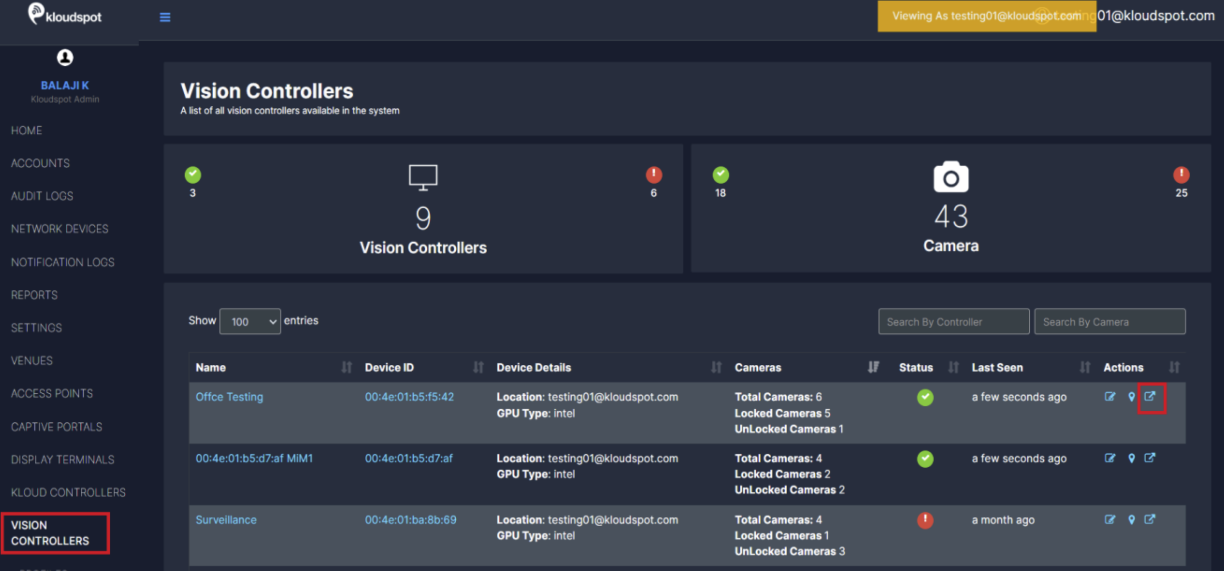
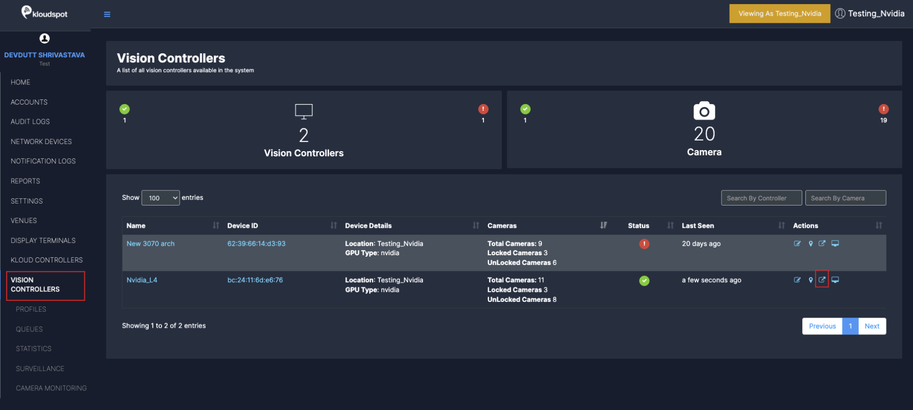
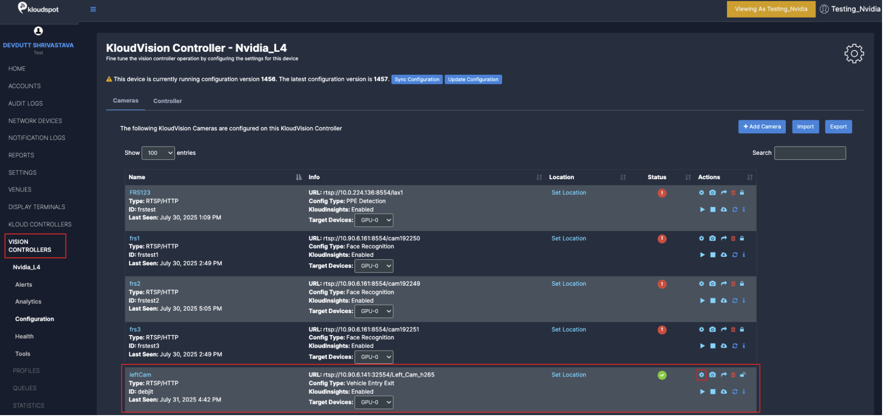
Navigate to VISION CONTROLLERS > Click on configuration icon for the desired controller.
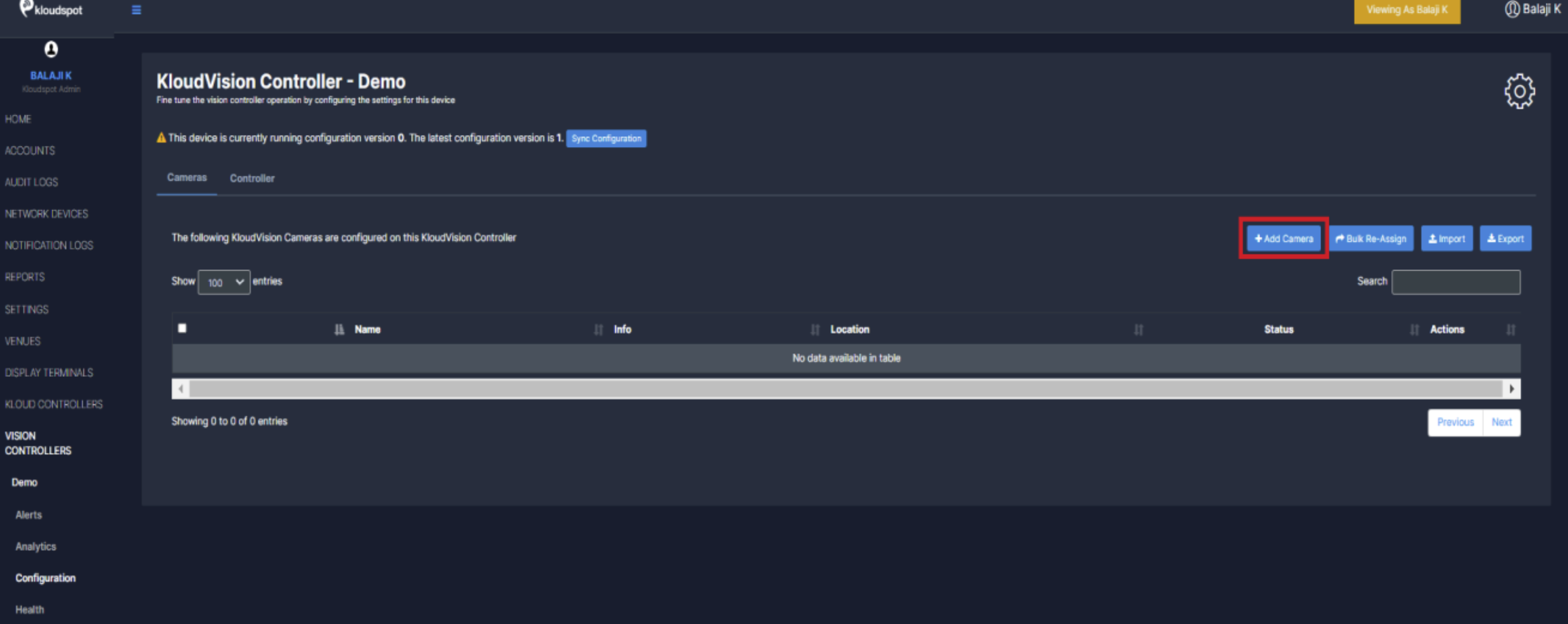
In the window that opens click on the +Add Camera button
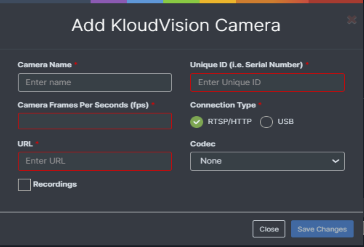
Enter the following in the popup window that opens and click the Save Changes button.
Name your camera.
  (We recommend naming your camera based on its location or
  using a clear, identifiable name for easy recognition)
Provide Unique ID for the Camera
(Assign a Unique ID to the camera for identification and management within the system)
Enter Camera Frames Per Seconds
(We recommend setting it to 25 FPS for optimal performance)
Choose the connection type (RTSP/HTTP or USB).
If we choose RTSP/HTTP we need to enter the URL you will link your camera feed from.
If using USB, provide the USB ID in the URL where the camera is connected (default is 0). (If unsure, please contact the Kloudspot Team for assistance.)
Select Codec based on the camera specifications (Refer to camera specifications)
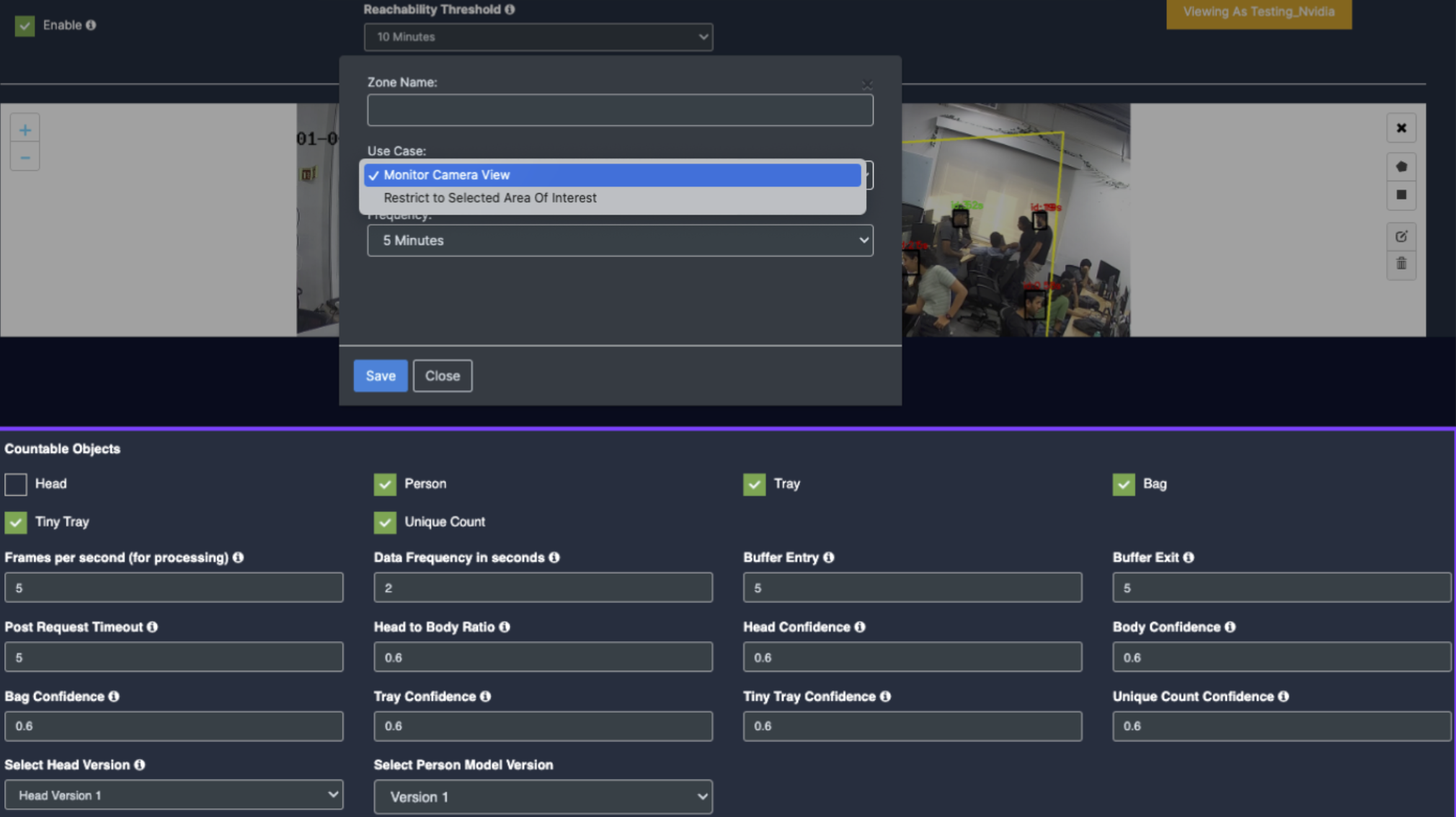
Once the camera is configured, additional settings can be adjusted based on its intended use case.
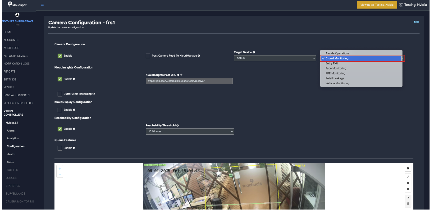
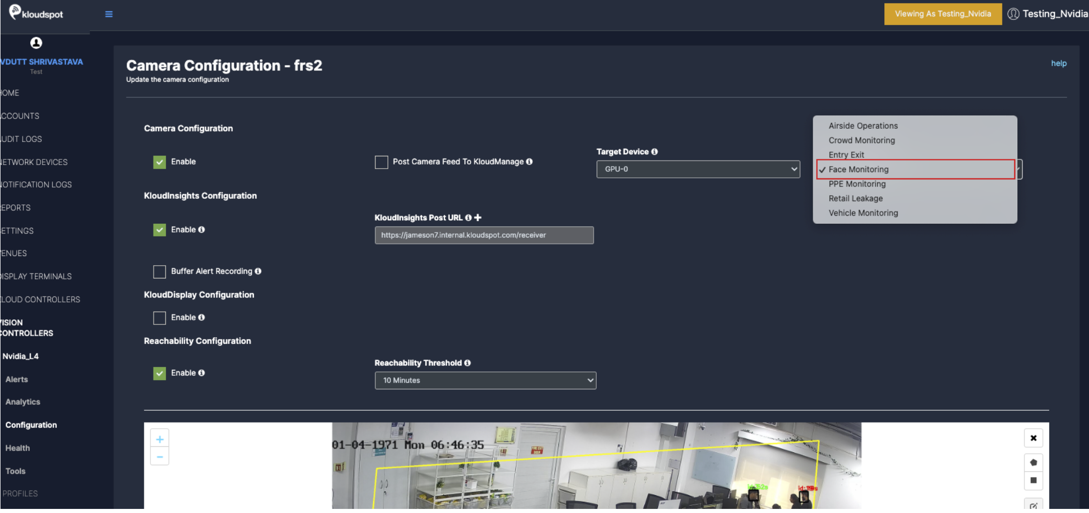
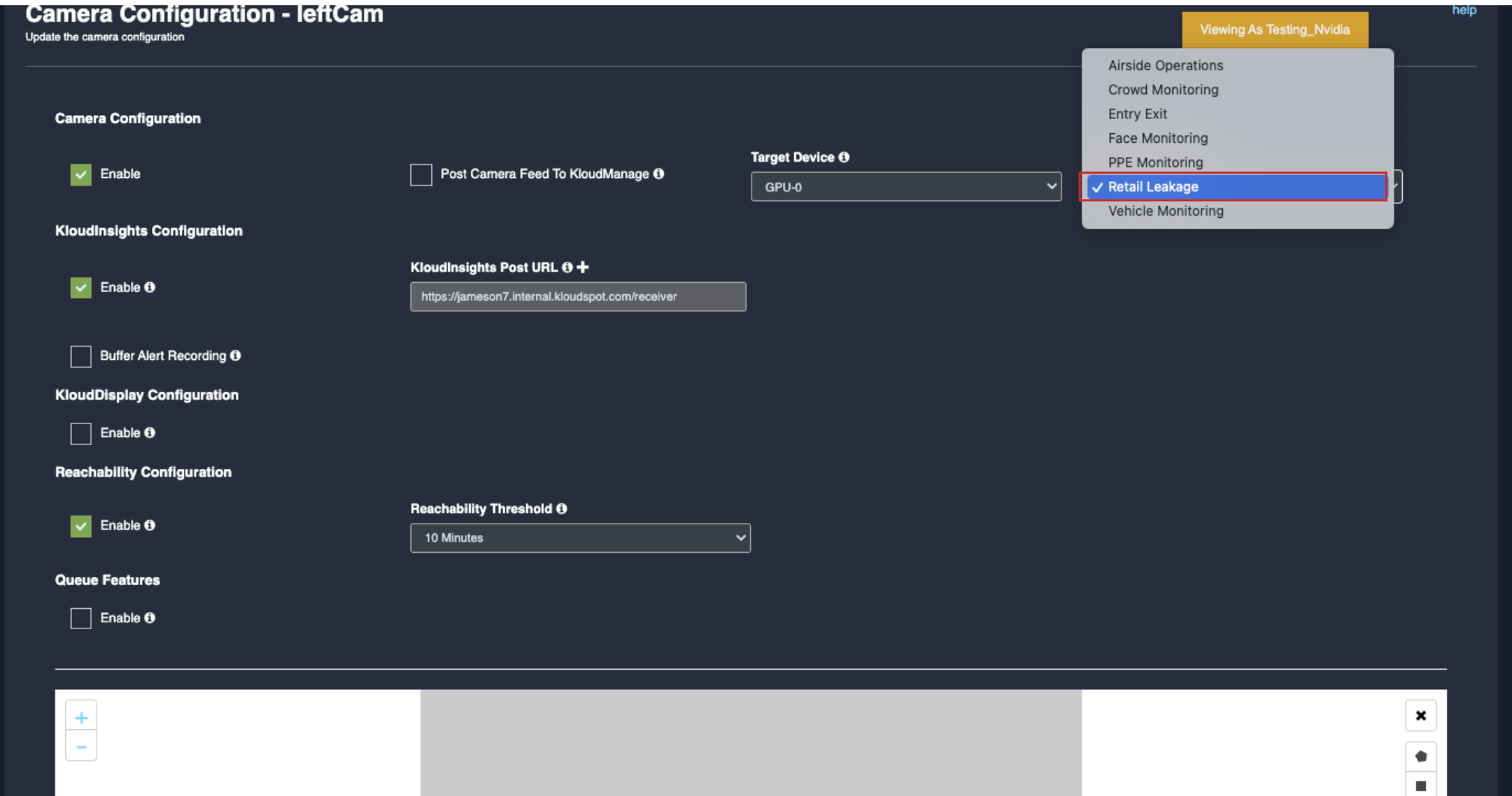
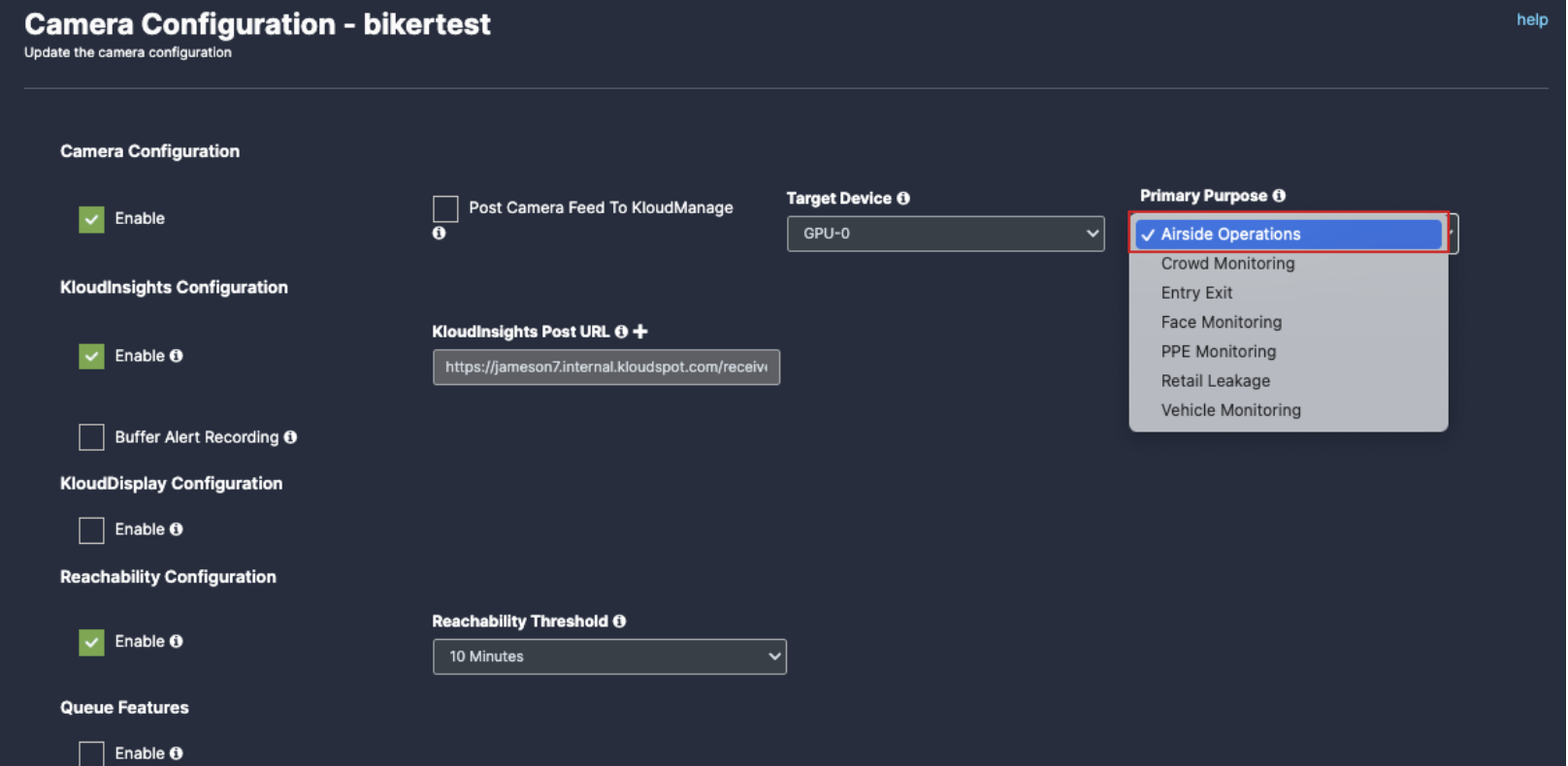
General Camera Configuration
To configure general camera configuration, navigate to Vision Controller>(Select Controller configuration)
In the camera list that opens, click on the Configuration button next to the camera you want to configure. Immediately the camera configuration window will open.
3. The configurations used as common in all use cases are given below.
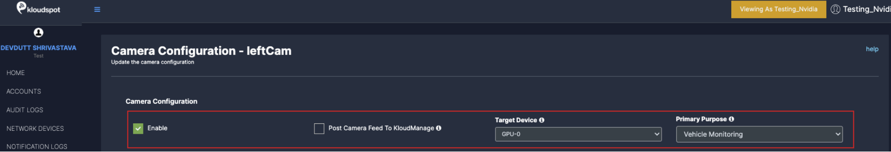
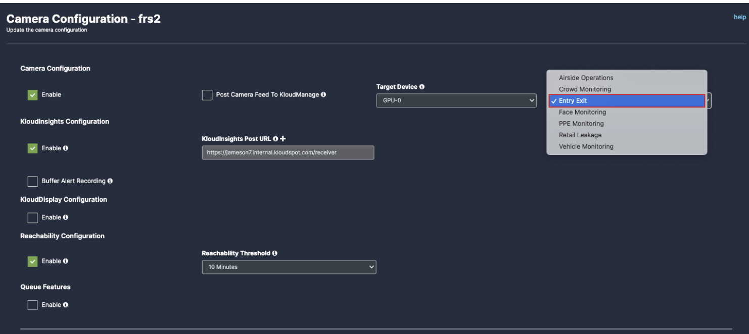
Enable: To activate any camera setup you desire, check enable checkbox.
Post Camera Feed: Enable this check box if you want to get camera status in KloudManage application.
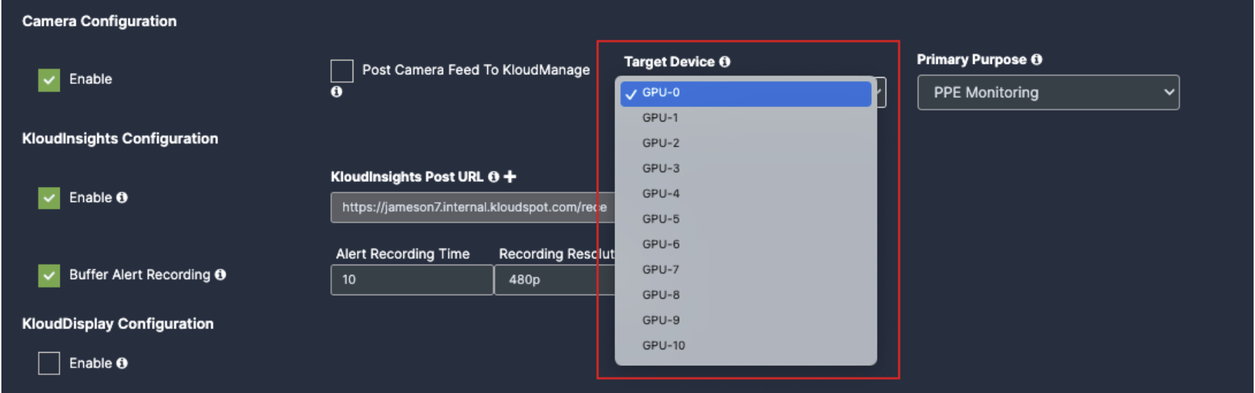
Target device: Select GPU as per your controller specifications.
7. Primary Purpose: Select the detection Use case.
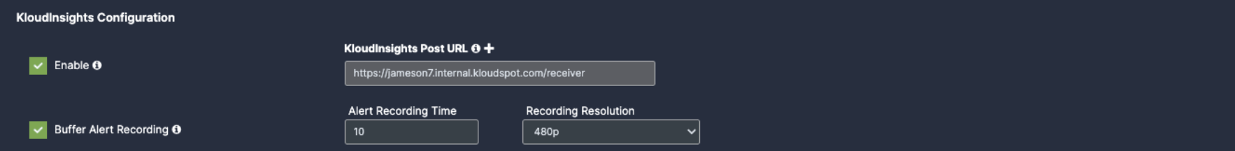
8. Enable KloudInsights: If you intend to share data from this camera with KloudInsights, please enable the designated checkbox. This will allow you to utilize the collected data to create new dashboards within the KloudInsights platform. Before proceeding, ensure integration between our Kloud Insights platform and KloudManage. Refer to the Integration with KloudManage section(Link) for detailed instructions on how to perform this integration.
KloudInsights Post URL: Enter your KloudInsights URL here.
Buffer Frame for Recording: Enable if you want a video/ image proof for the incidents happened, should have integration with KloudInsights.
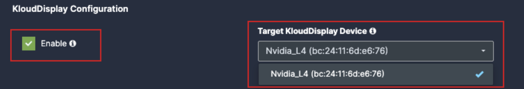
11. Enable KloudDisplay: Check this option to configure a KloudDisplay to react to the events generated by the camera. Click on the Target KloudDisplay dropdown to tie this camera with a KloudDisplay. Examples of this could be displaying a ‘Please wear a mask’ message on the display when the camera detects a person without a facemask.
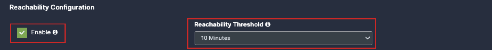
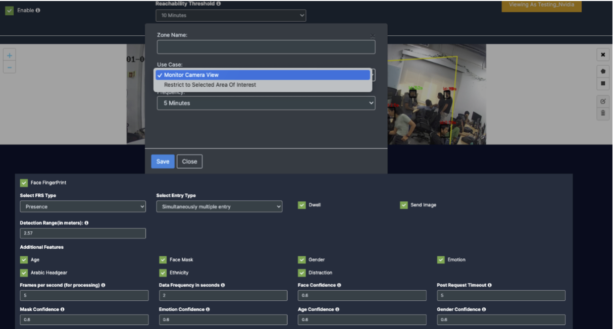
12. Reachability: It notifies you if the camera is inactive for an extended period. For example, If you set reachability to 10 you will get a notification if the camera is inactive for more than 10 minutes.
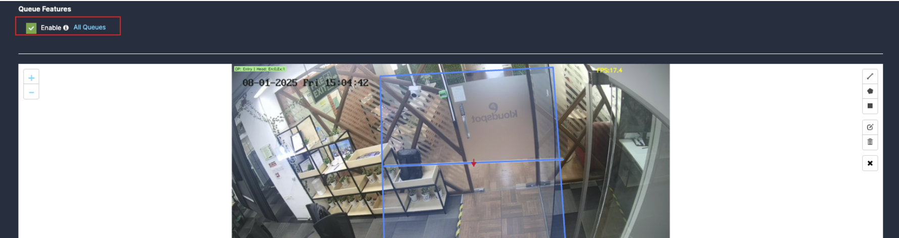
13. Queue feature: Enable the Queue checkbox for wait time and queue related data.(link queue)
14. Countable objects:
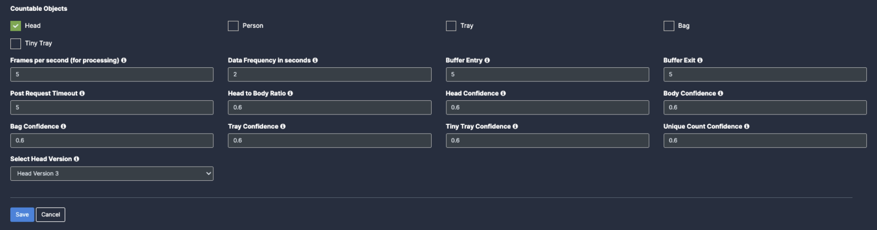
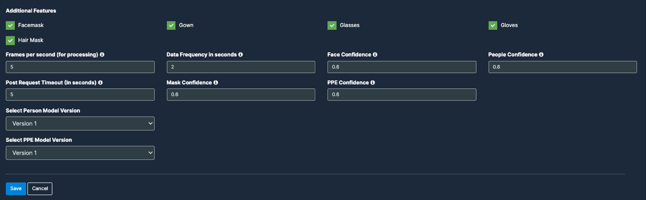
Frames per second (for processing): These are the number of frames used by Vision Controller every second for data processing. KloudVision does not use all the frames emitted from the camera in a second. Higher values provided in this field may increase CPU/GPU usage.
Data Frequency in seconds: This value indicates how long Vision controller aggregates data before sending it out to KloudInsights. A lower value may increase the data frequency and result in a faster response. A higher value results in a delayed response.
Buffer Entry/Exit:
Post Request Timeout (in seconds): This value indicates how long KloudVision waits and retries to send the payloads out to KloudInsights until it reaches the preset timeout period.
Head to Body Ratio: Minimum head-to-body ratio required to classify a person as a child. If detected ratio meets/exceeds this value, the model identifies the individual as a child
Head Confidence: Minimum confidence score for head detection. Only detections scoring at or above this threshold are considered valid by the model.
Body Confidence: Minimum confidence score for person detection. Only detections scoring at or above this threshold are considered valid by the model
Bag Confidence: Minimum confidence score for bag detection. Only detections scoring at or above this threshold are considered valid by the model.
Tray Confidence: Minimum confidence score for tray detection. Only detections scoring at or above this threshold are considered valid by the model
Tiny Tray Confidence: Minimum confidence score for tiny tray detection. Only detections scoring at or above this threshold are considered valid by the model
Unique count Confidence: Minimum confidence required for the model to match two person detections as the same individual. Used for accurate unique person counting
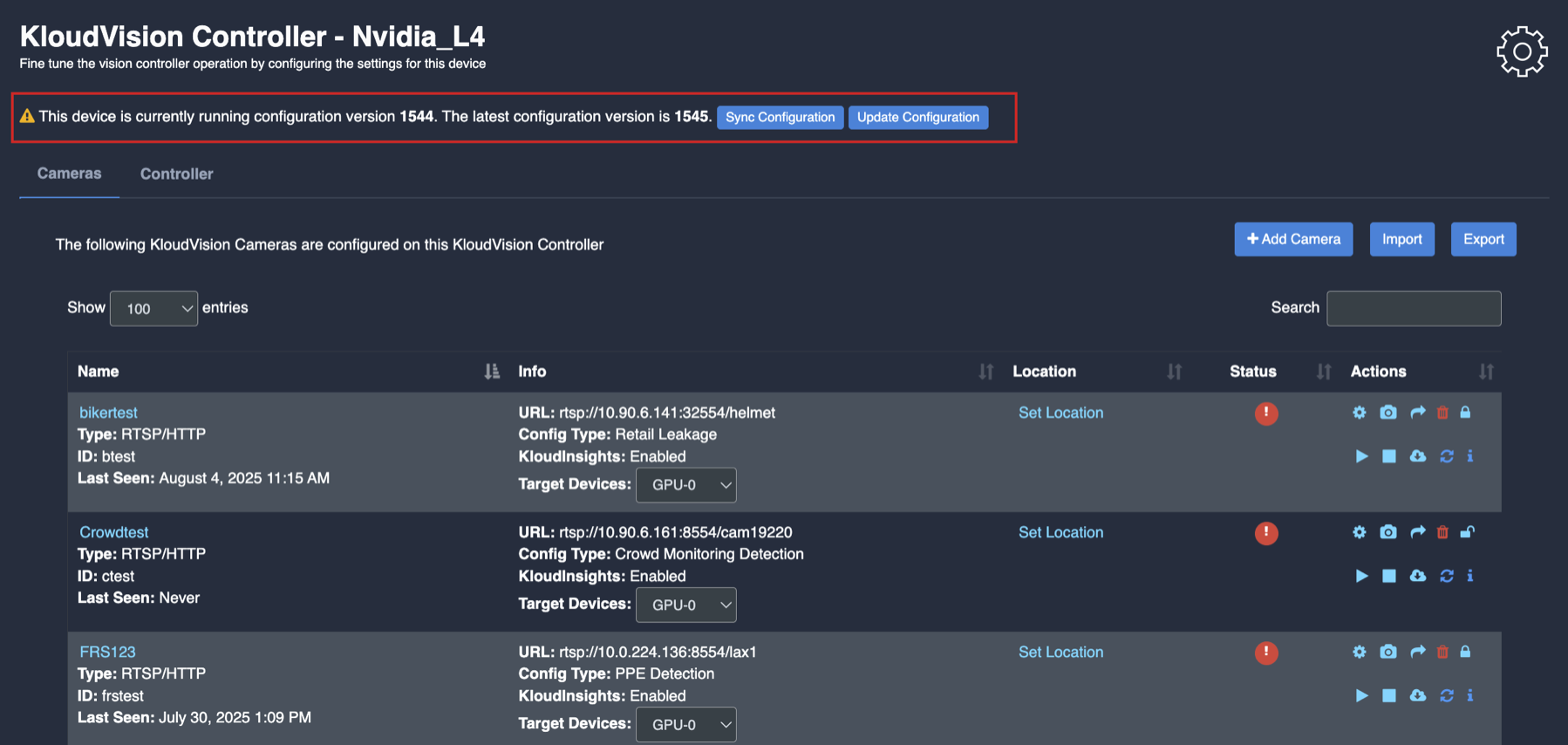
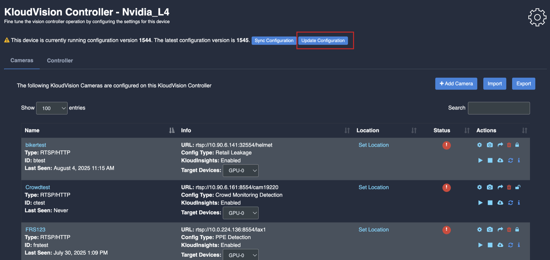
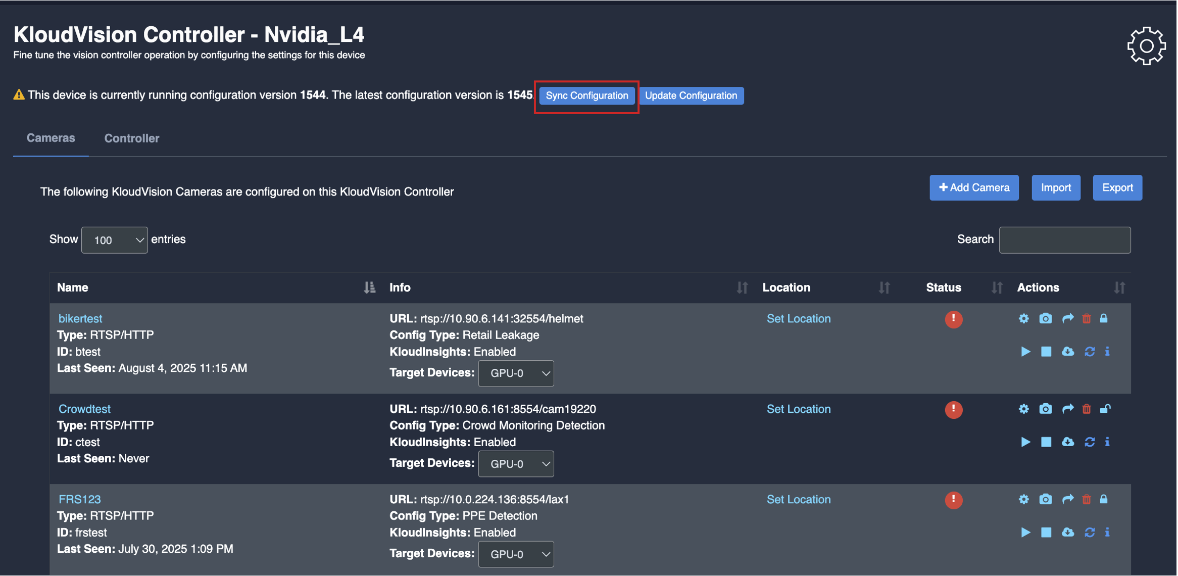
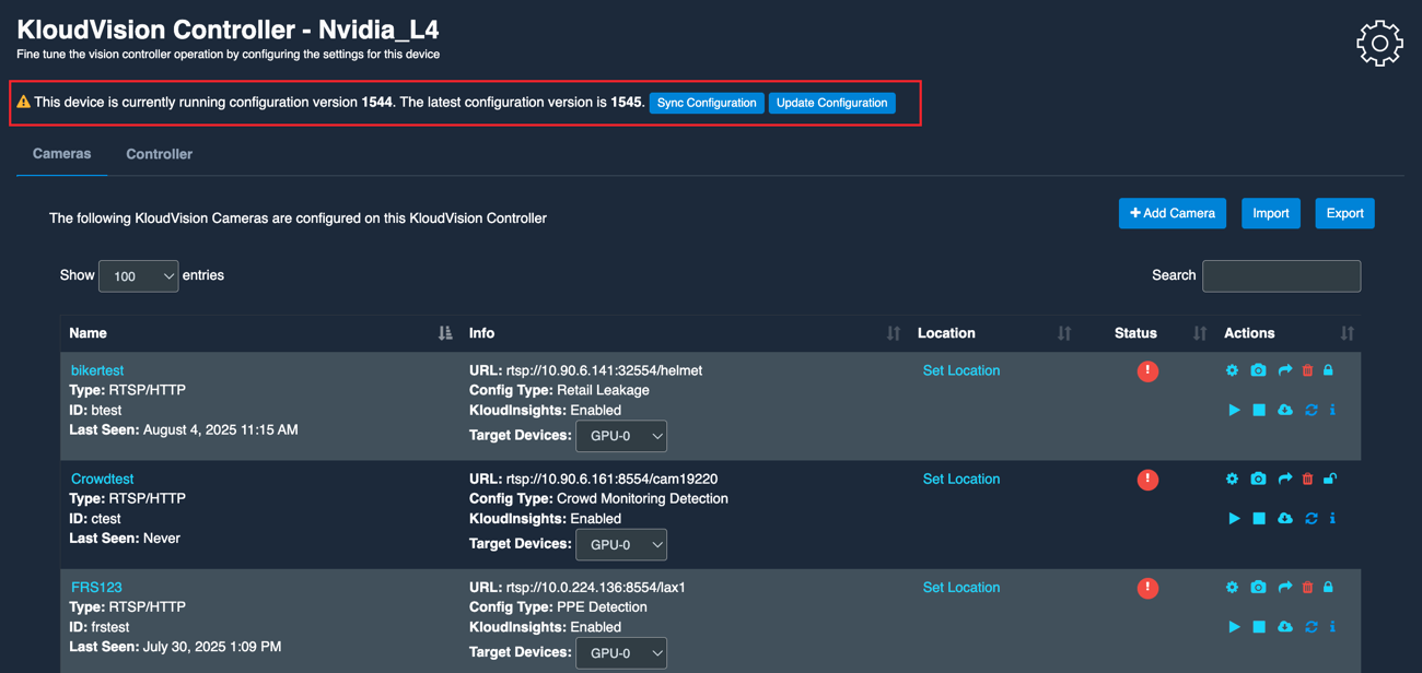
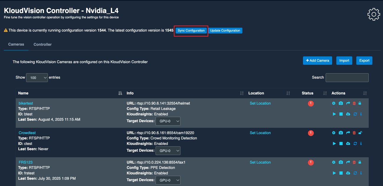
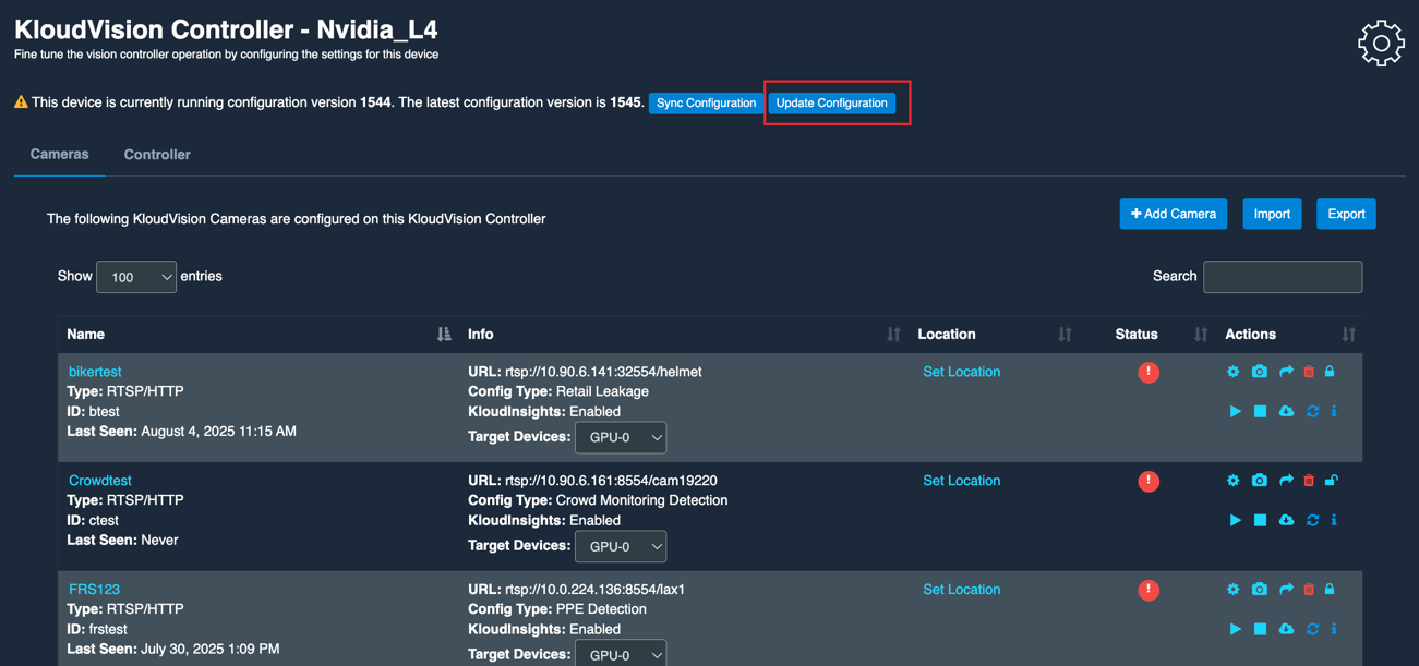
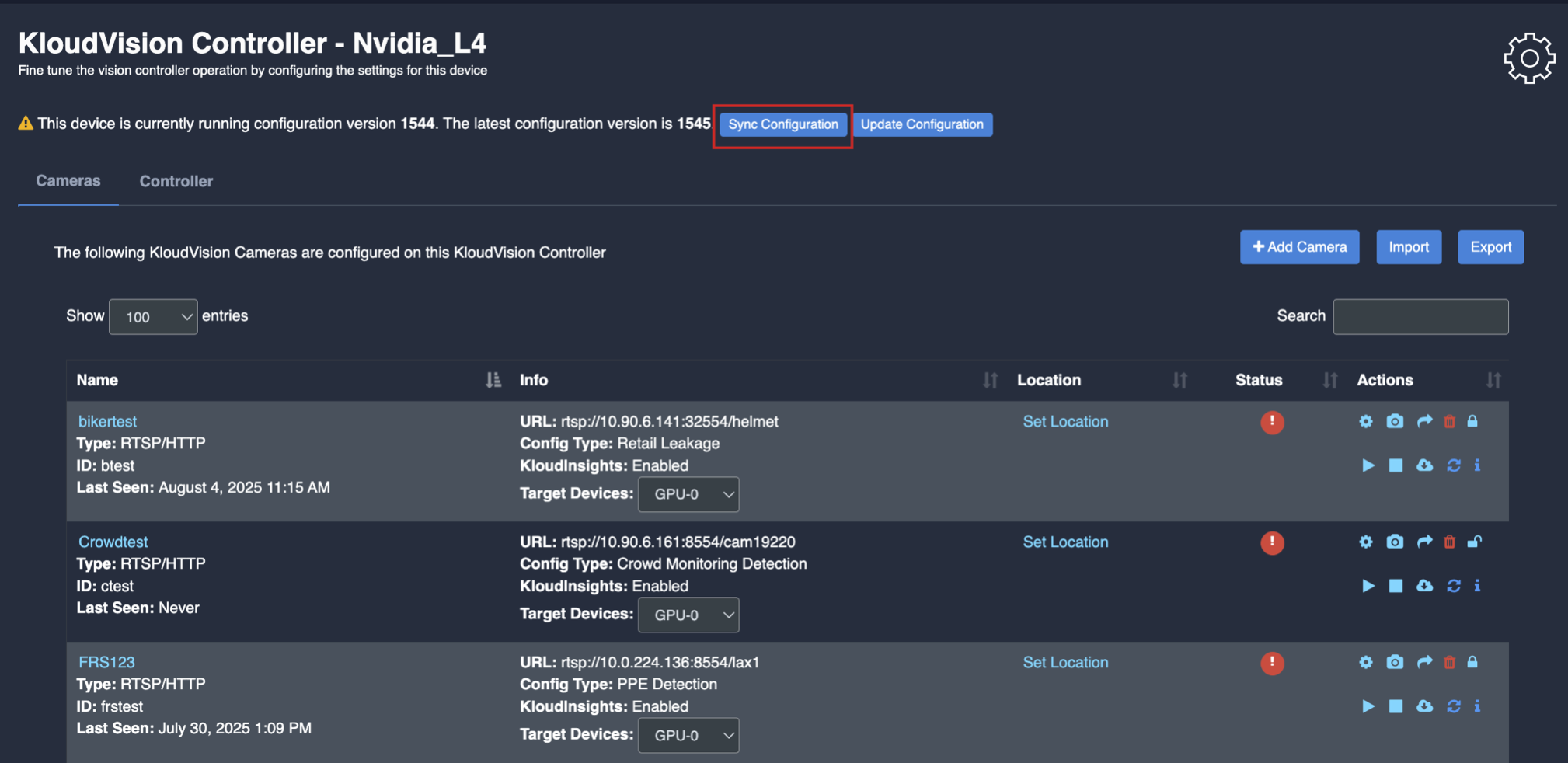
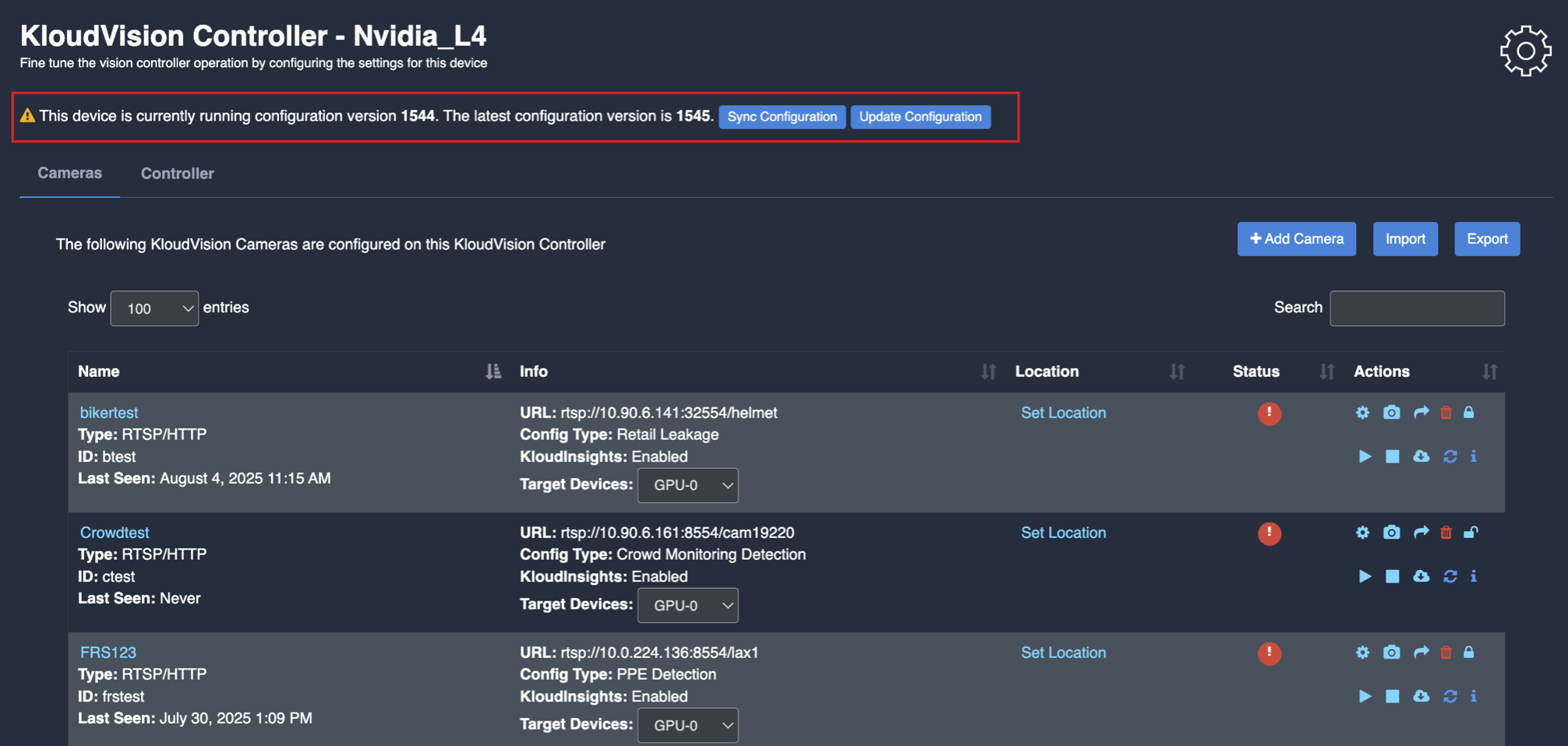
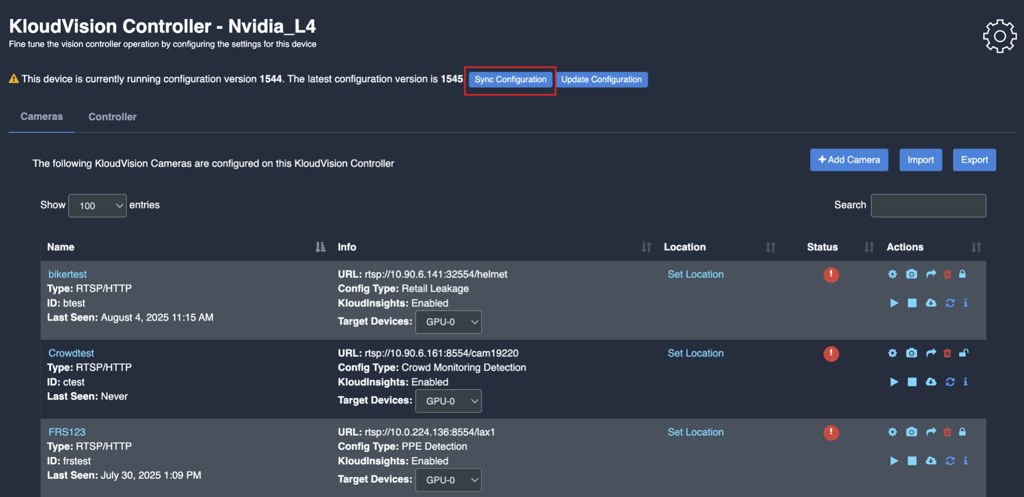
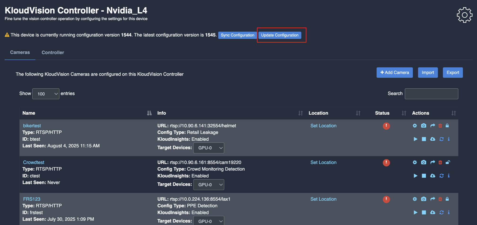
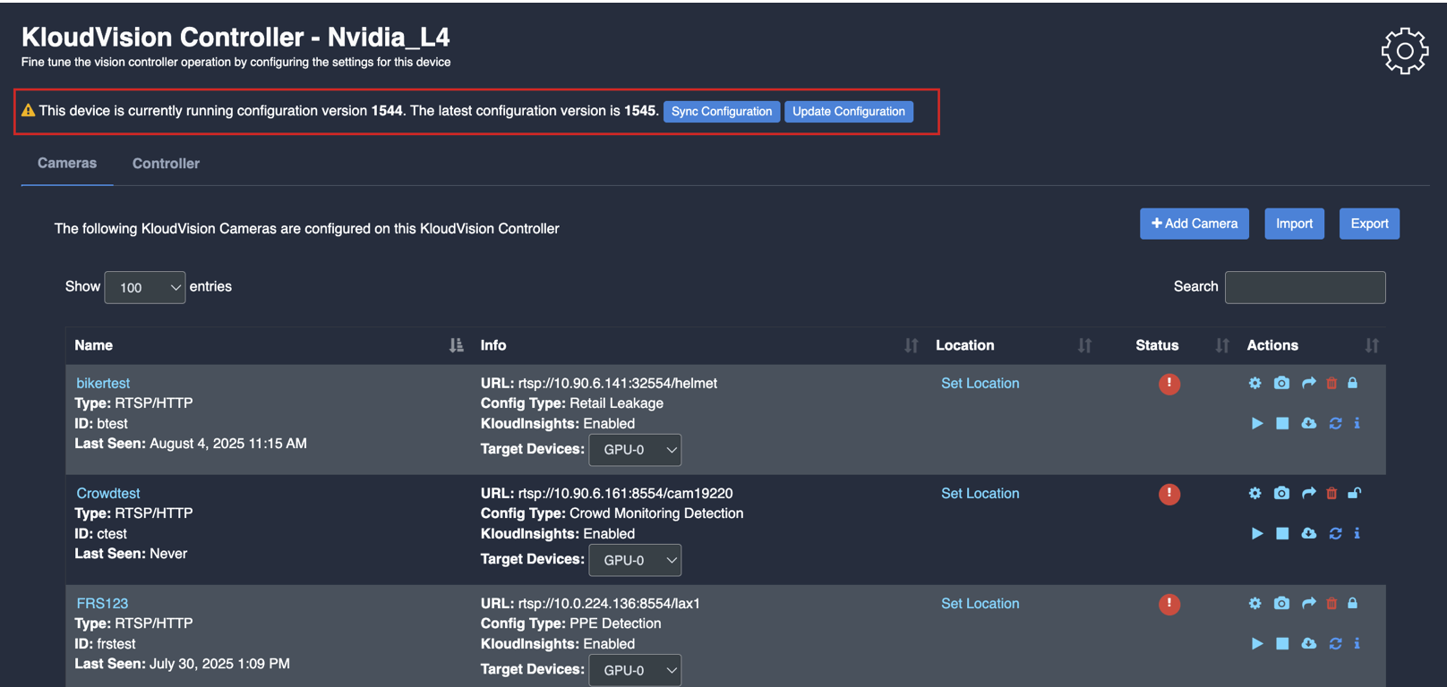
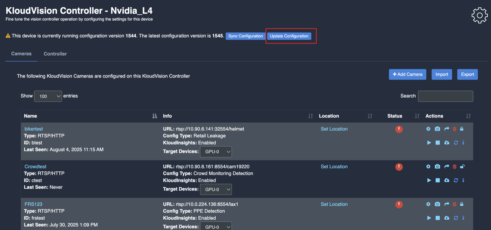
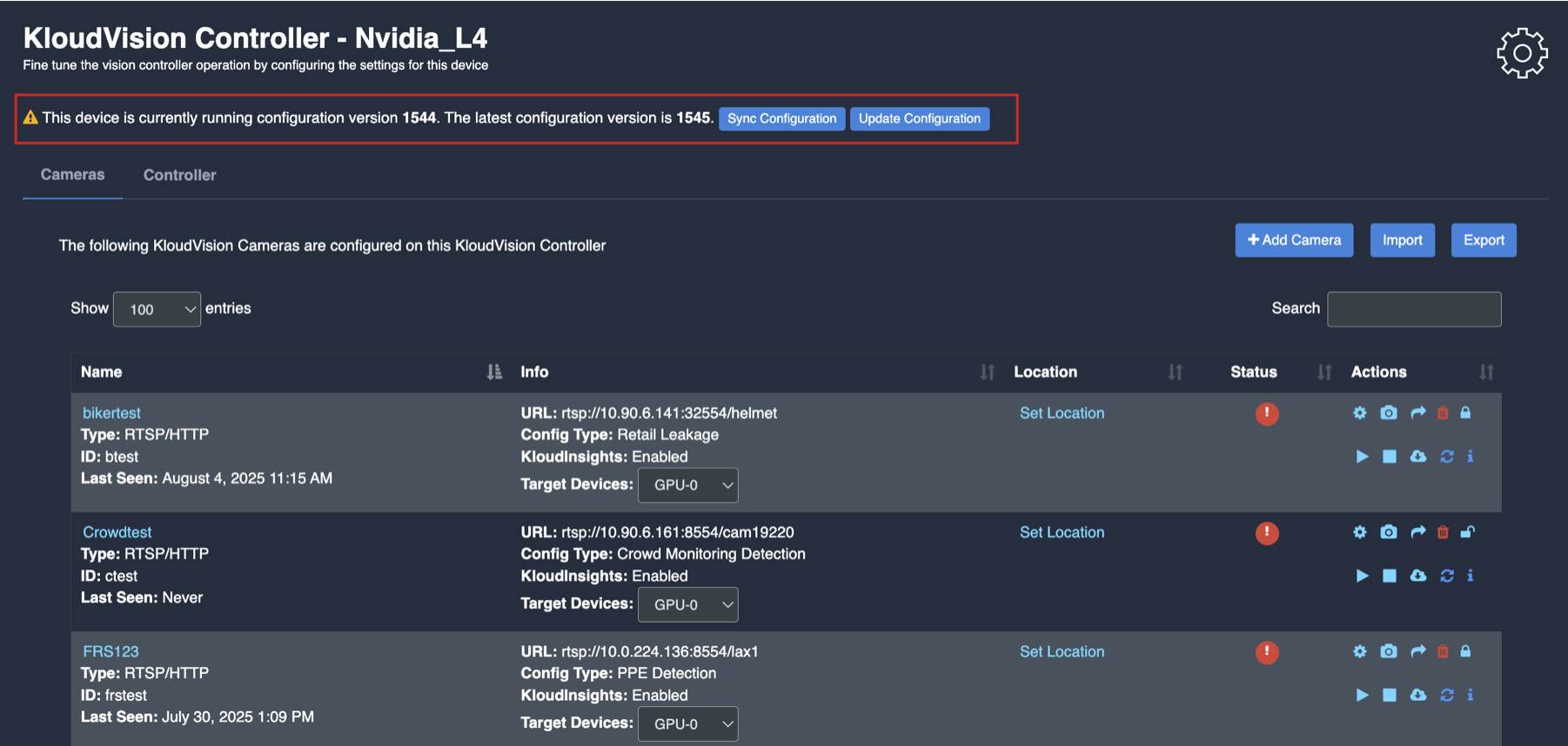
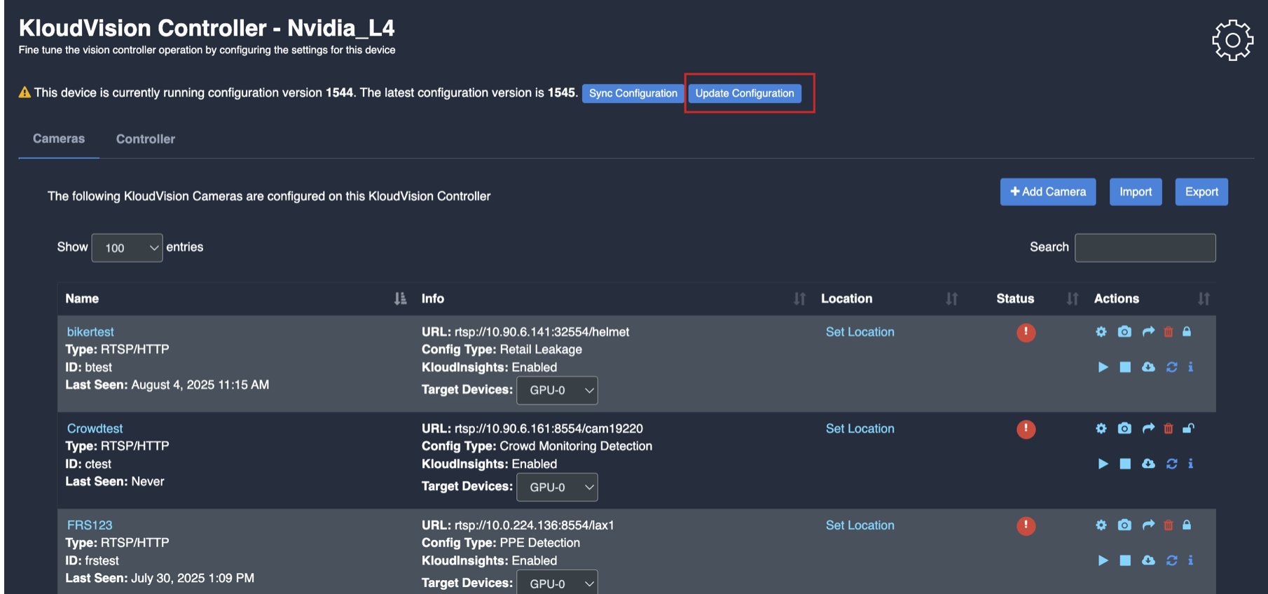
Update/ sync Configuration:
Once you perform any change in the controller or update any features/ use cases for camera you need to sync it.
There are 2 types of syncing process:
Sync the configurations
Update the Configurations
Click on sync configuration to restart the complete system syncing process. Basically for the initial camera setup and while any controller configuration update. (It will restart the docker and sync all the performed changes)
4. Click on the update configuration to recent changes in the system without any downtime. (General configuration sync)
Crowd Monitoring
Before you begin configuring the use cases, you should first configure the camera’s general configuration. Refer to the General Camera Configuration section for instructions.
Then, select the Crowd Monitoring from the dropdown list
Next, Scroll down and choose your preferred use cases. You can choose multiple Features.
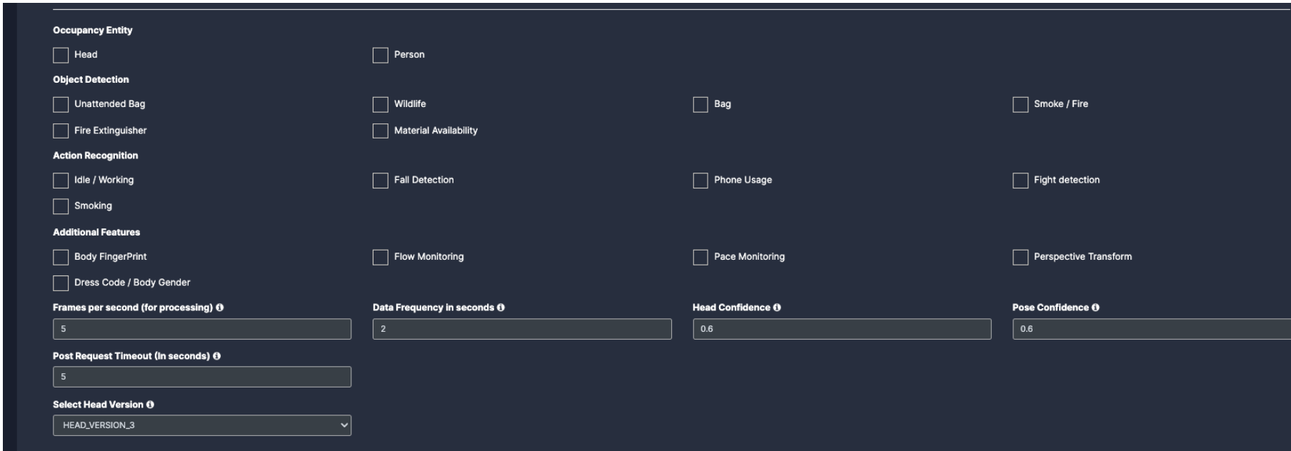
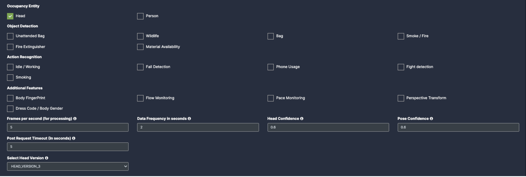
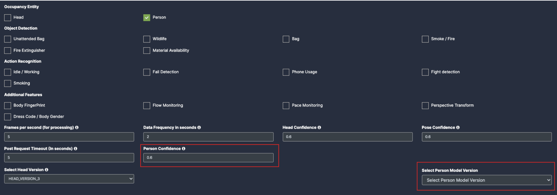
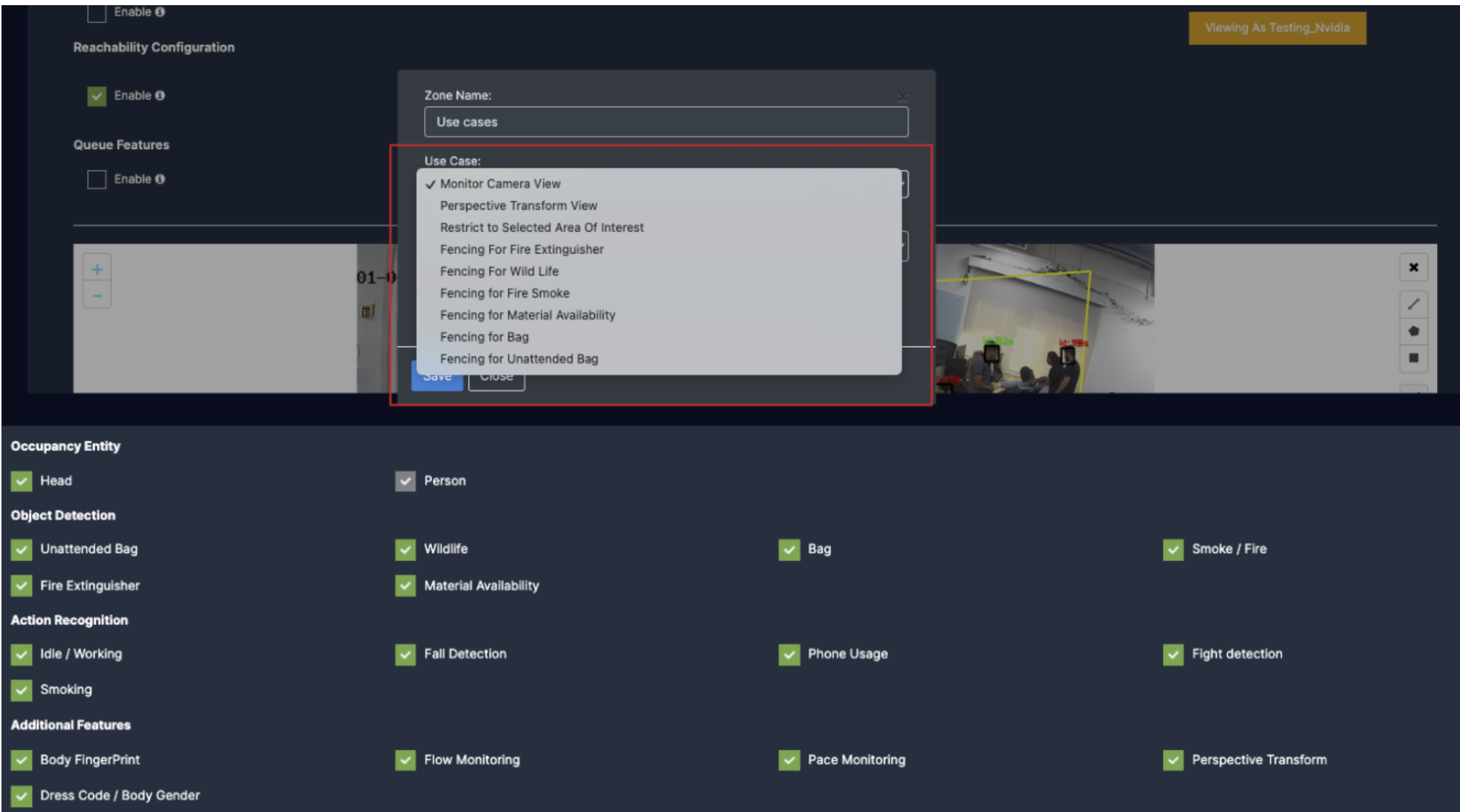
Occupancy Entity: (Exact number of people in the defined area)
Head: To capture any persons head count, click on this check box and fill the confidence rate for it.
Person: To capture any person count, click on this check box and fill the confidence rate and model version for it.
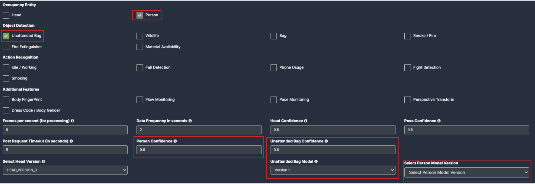
Object detection: (Identify known objects)
Unattended Bag: Once you click on the check box of unattended bag, the person will be auto enabled. You will see the Person confidence and version with bag model added below which needs to be filled.
Wildlife: Once you click on the check box of wildlife their respective dropdowns will be added below for the respective feature detection.
Bag: Once you click on the check box of Bag their respective dropdowns will be added below for the respective feature detection.
Smoke/fire: Once you click on the check box of Smoke/fire their respective dropdowns will be added below for the respective feature detection.
Fire extinguisher: Once you click on the check box of Fire extinguisher their respective dropdowns will be added below for the respective feature detection.
Material Availability: Once you click on the check box of Material Availability their respective dropdowns will be added below for the respective feature detection.
Note: You need to Draw a separate ROI(Link) for all object detection Use cases.
6. Action Recognition: (action a person (or object) is performing)
Idle/Working: Once you click on the check box of Idle/Working, the person checkbox will be auto enabled and their respective dropdowns will be added below for the respective feature detection.
Fall Detection: Once you click on the check box of fall detection, the person checkbox will be auto enabled and their respective dropdowns will be added below for the respective feature detection.
Phone usage: Once you click on the check box of Phone usage, the person checkbox will be auto enabled and their respective dropdowns will be added below for the respective feature detection.
Fight Detection: Once you click on the check box of Fight Detection, the person checkbox will be auto enabled and their respective dropdowns will be added below for the respective feature detection.
Smoking: Once you click on the check box of Smoking, the person checkbox will be auto enabled and their respective dropdowns will be added below for the respective feature detection.
Note: You need to Draw a separate ROI(Link) for all Action recognition Features.
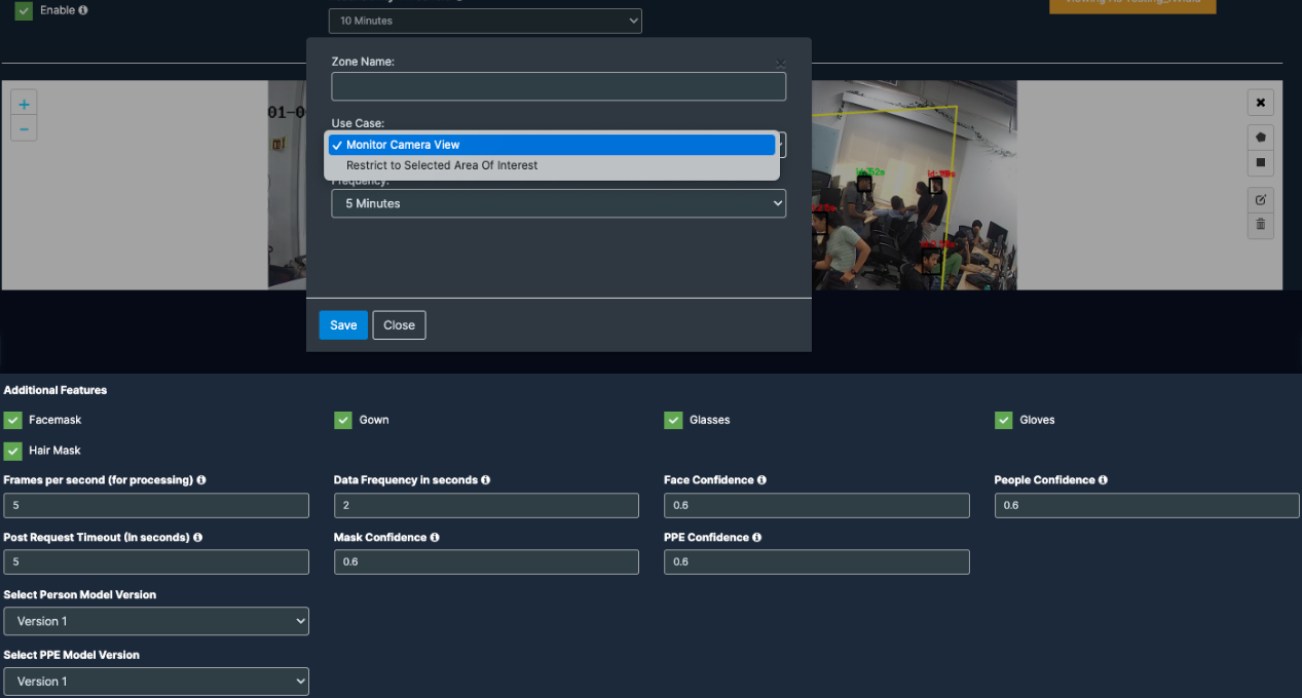
Additional Features:
Body Fingerprint: Once you click on the check box of Body Fingerprint, the person checkbox will be auto enabled and their respective dropdowns will be added below.
Dress Code/ Body Gender: Once you click on the check box of Dress Code/ Body Gender, the person checkbox will be auto enabled and their respective dropdowns will be added below.
Flow Monitoring : Click on the check box of flow monitoring to enable the use case.
Pace Monitoring: Click on the check box of Pace monitoring to enable the use case.
Perspective Transform: Click on the check box of Perspective Transform to enable the use case.
Note: You need to Draw a separate ROI(Link) for all Additional features.
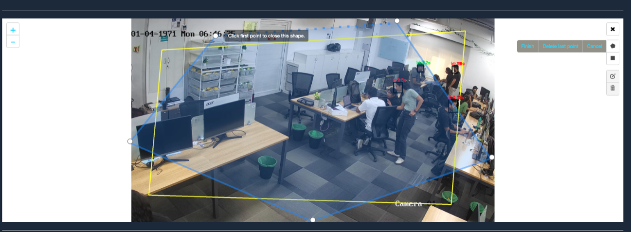
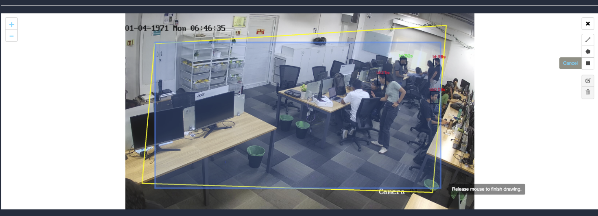
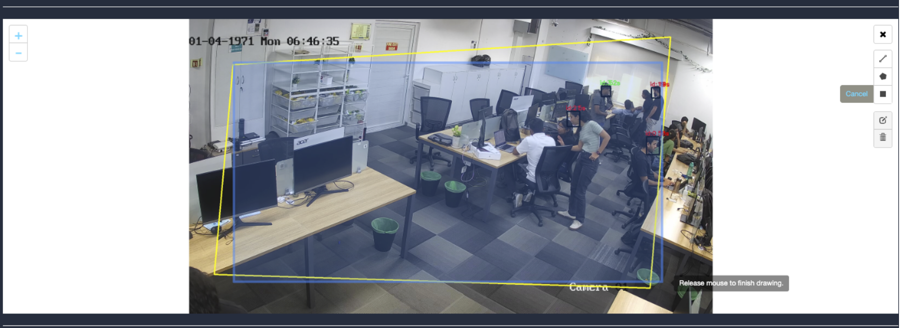
Draw ROI (region of interest) on the camera frame.
ROI in camera frames can help to improve efficiency, accuracy, and reduce storage requirements.
ROI must be added if kiosk mode is enabled. Otherwise, it is optional. If ROI is not added, the model will detect the entire frame.
For face detection, ROI can be drawn in two ways.
Using the polygon tool
Using the rectangle tool.
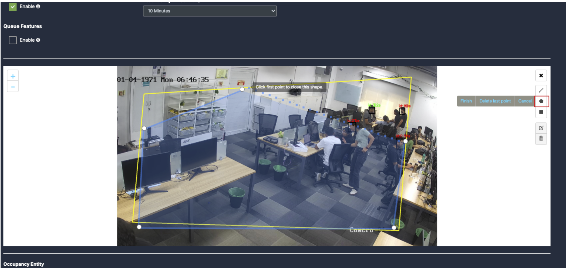
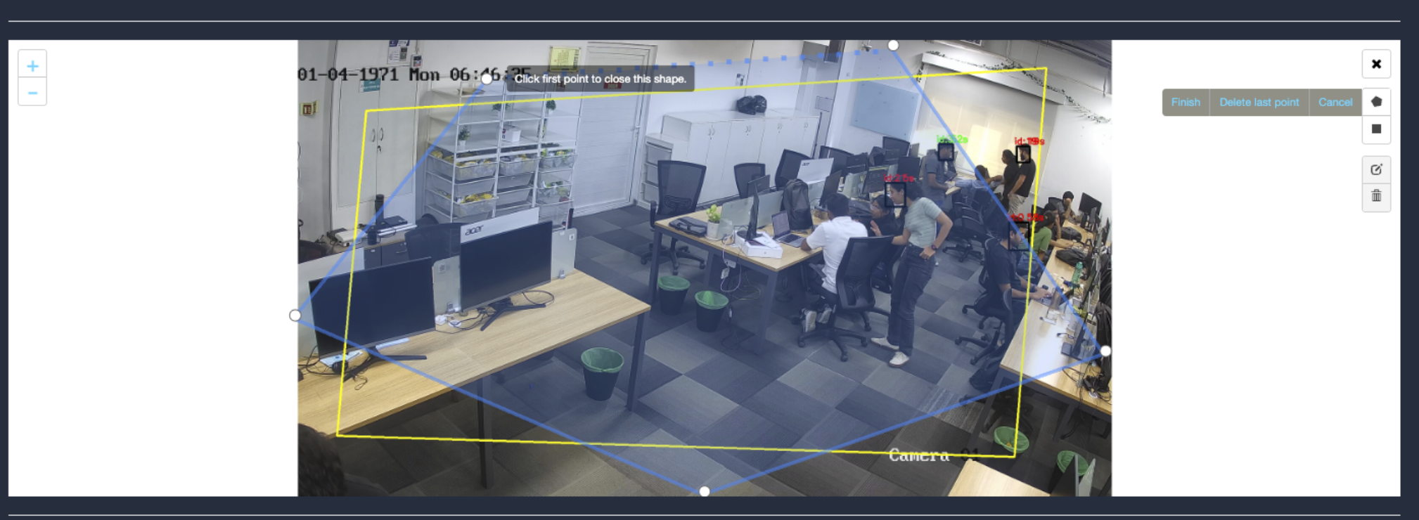
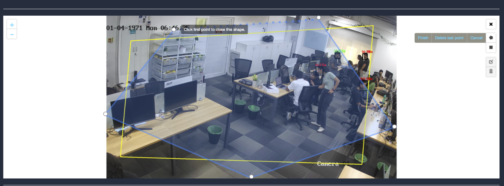
Draw ROI using the Polygon tool.
Click on the Polygon tool button from the camera frame.
Then connect the dots and draw the polygon in the space where you want to draw the ROI. It should have more than 2 points.
After drawing, click the Finish button to complete the drawing.
With this ROI you can achieve the below features:
Unattended bag
Wildlife
Bag
Smoke/Fire
Fire Extinguisher
Flow Monitoring
Perspective Transform
Material Availability
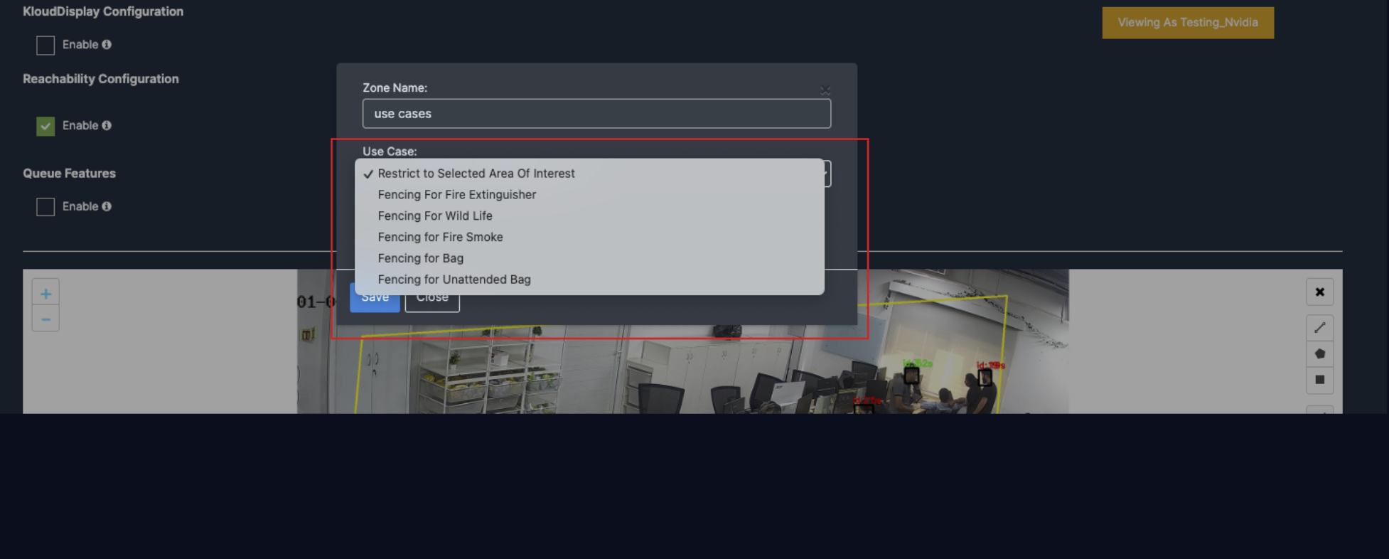
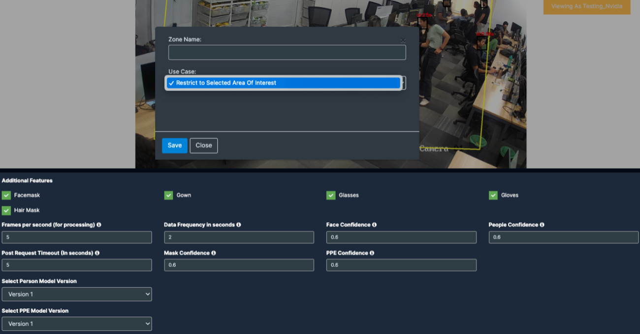
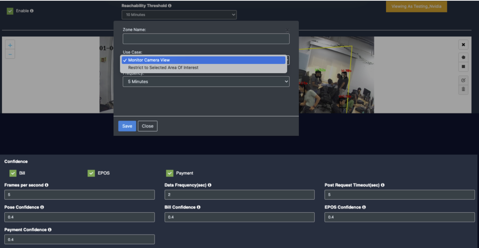
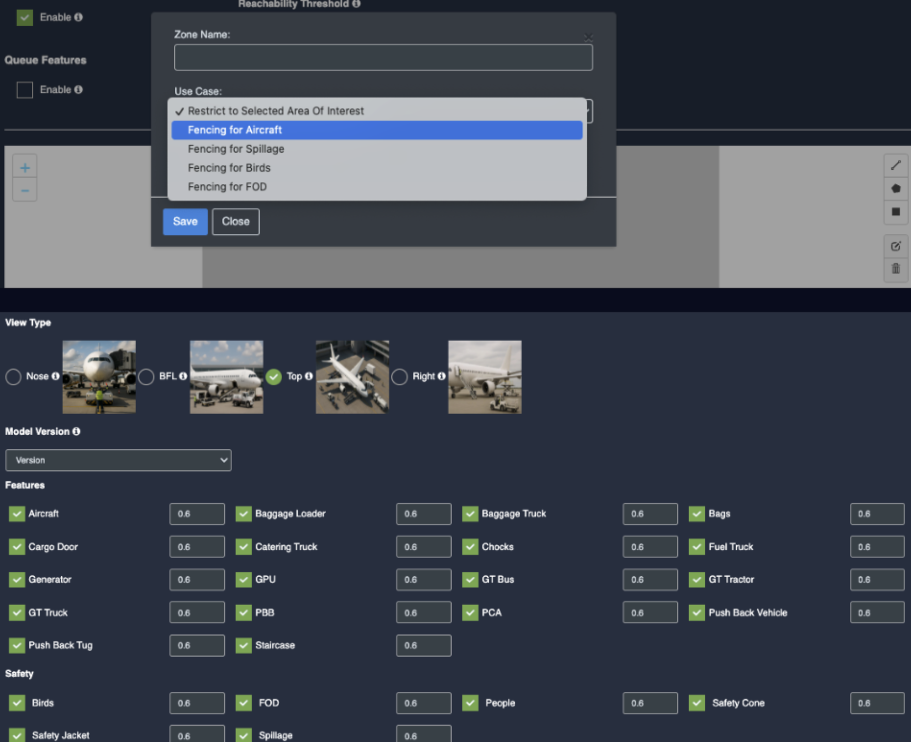
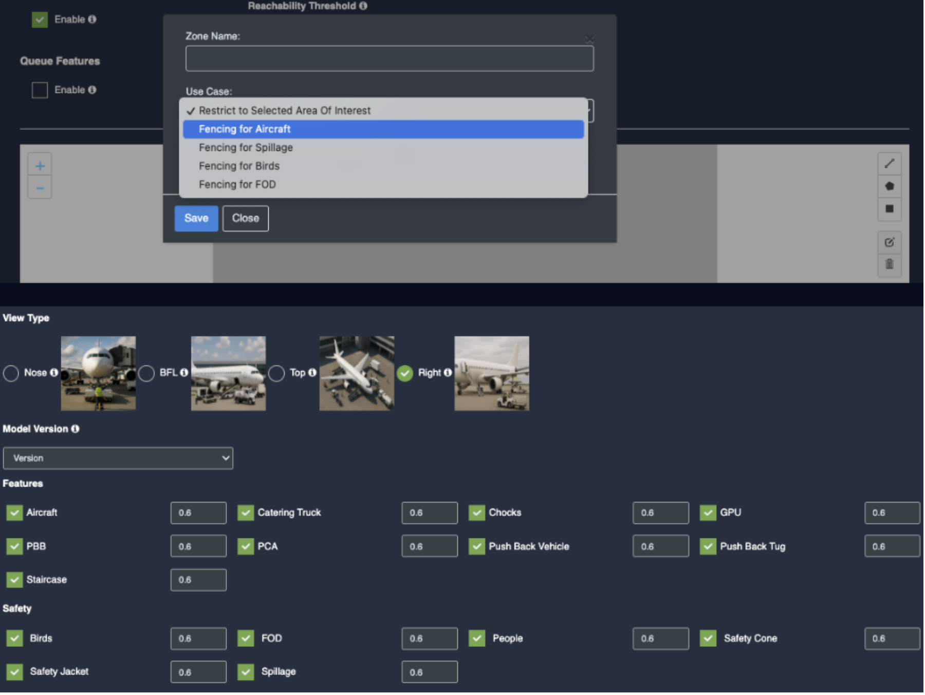
Enter the zone name in the popup window that opens and click the Save button.
New ROI zone added successfully.
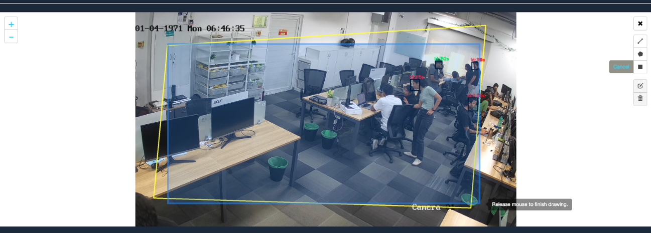
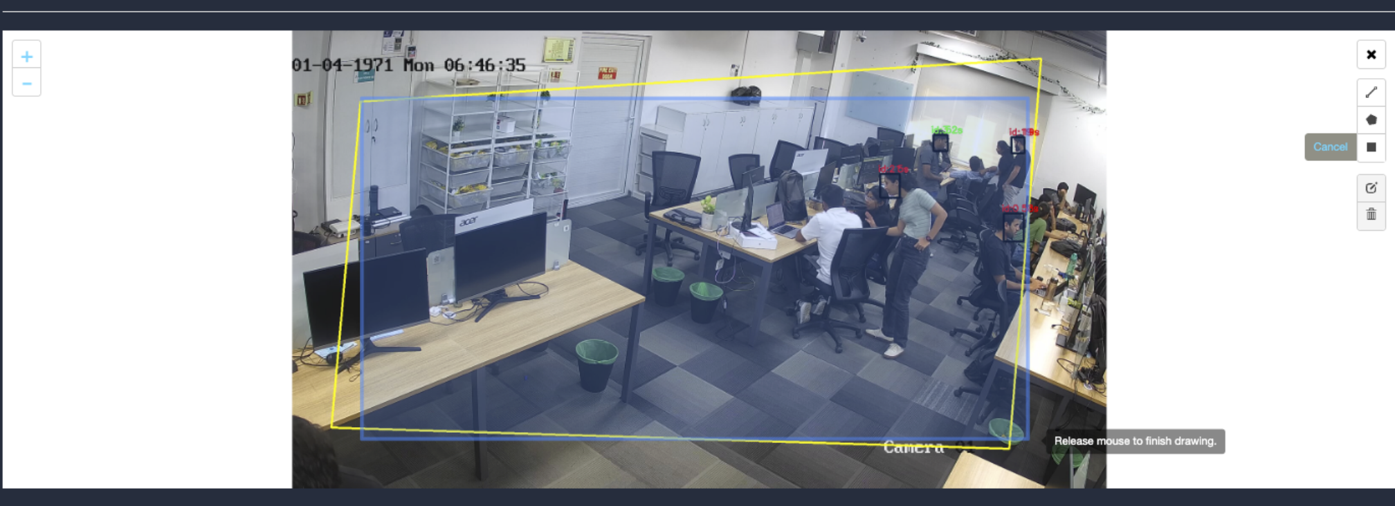
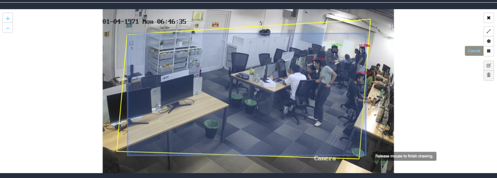
Draw ROI using the rectangle tool.
Click on the Rectangle tool button from the camera frame.
Then draw the rectangle where you want to focus the camera.
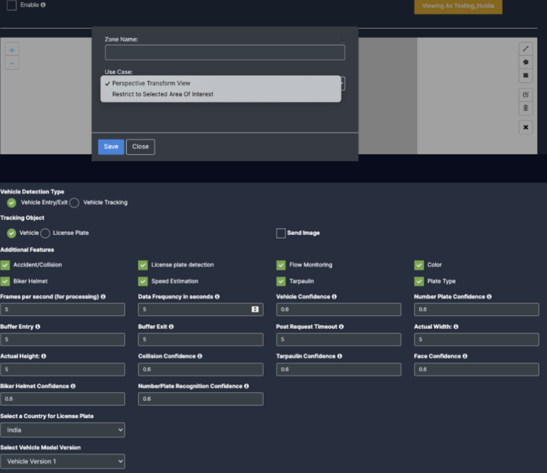
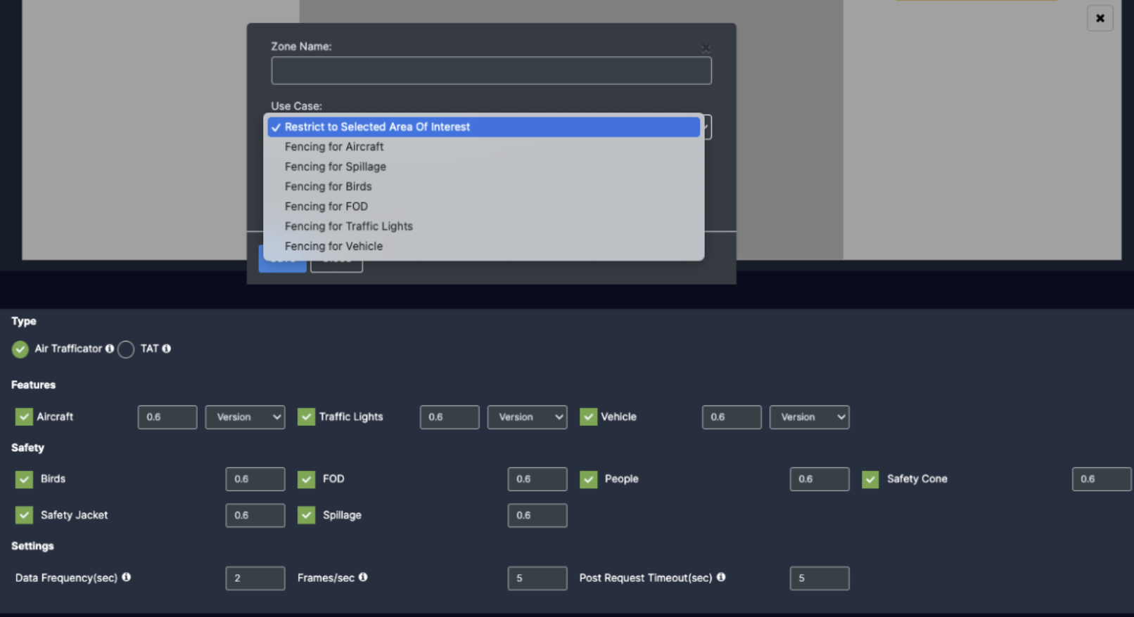
Then enter the zone name and select Restrict to selected area of interest option from the dropdown list and click the Save button.
Detection will only happen when people enter this zone.
With this ROI you can achieve the below Features:
Object Detection
Action Recognition
Additional Features
Once the Use case Configuration is done, click on save.
Your Camera is configured for Crowd monitoring.
Update/ sync Configuration:
Once you perform any change in the controller or update any features/ use cases for camera you need to sync it.
There are 2 types of syncing process:
Sync the configurations
Update the Configurations
Click on sync configuration to restart the complete system syncing process. Basically for the initial camera setup and while any controller configuration update. (It will restart the docker and sync all the performed changes)
Click on the update configuration to recent changes in the system without any downtime. (General configuration sync)
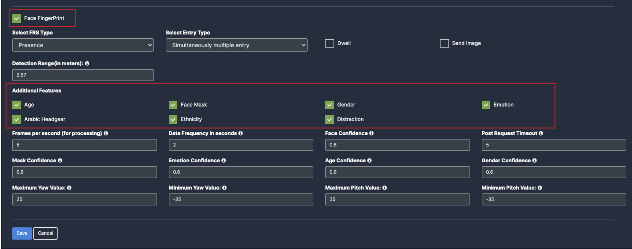
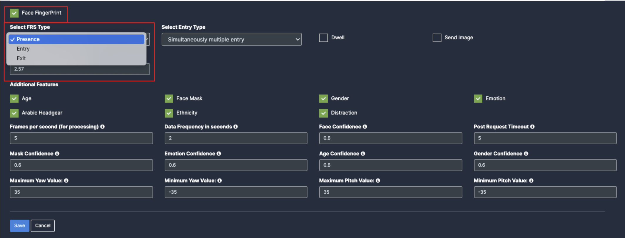
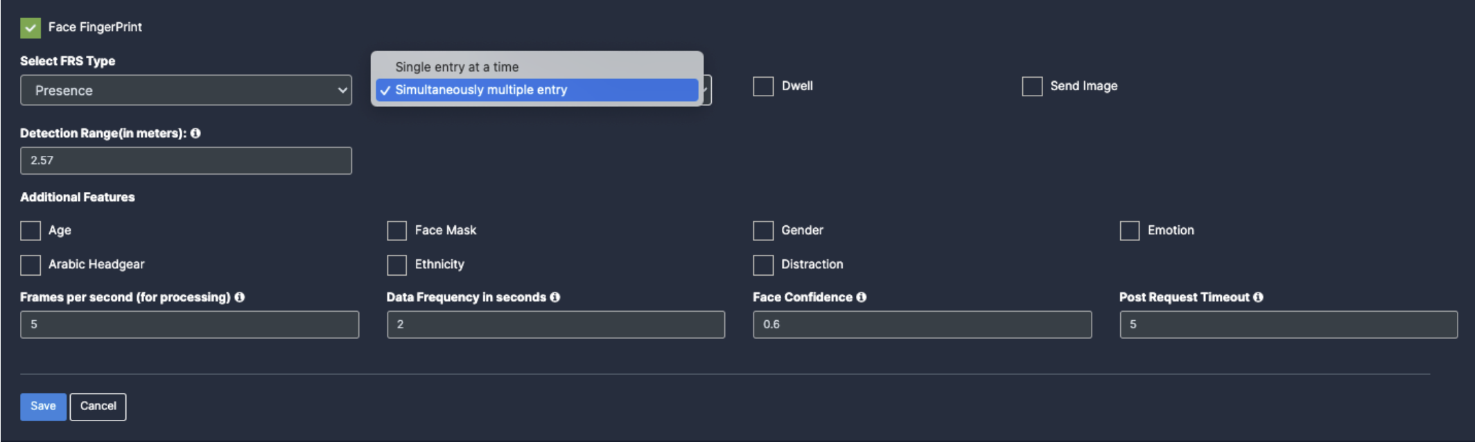
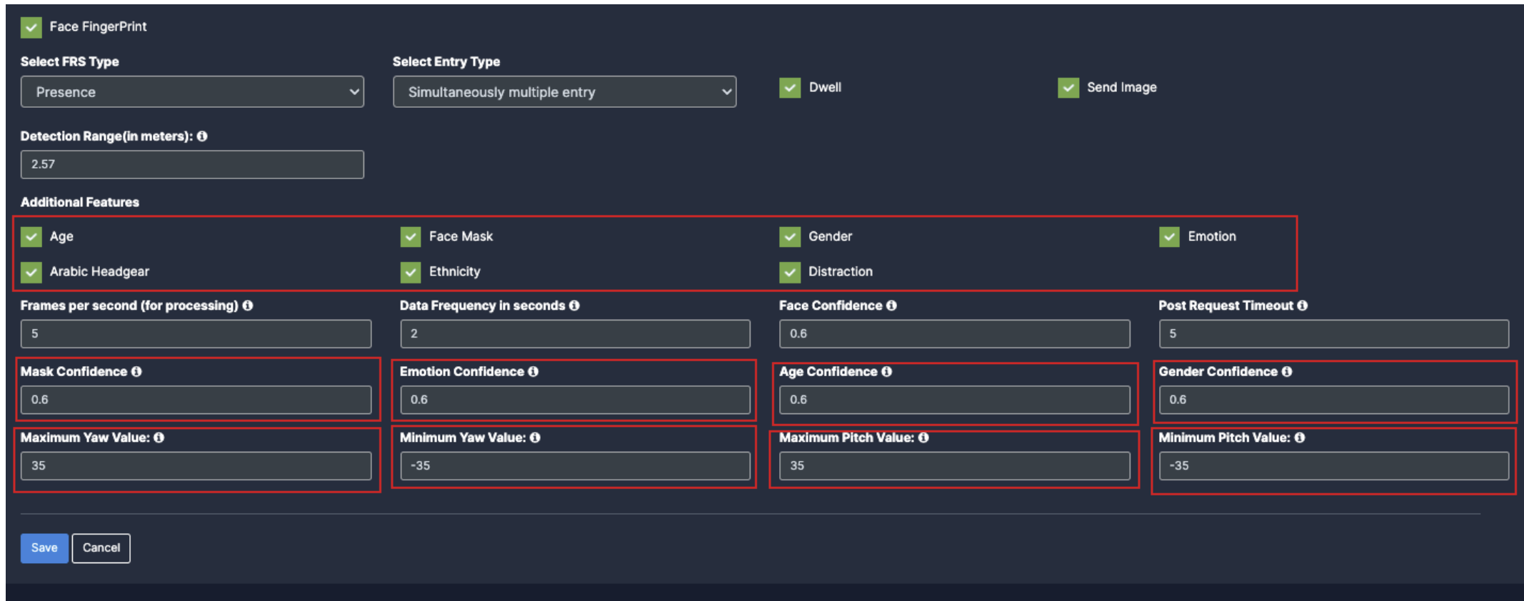
Face Monitoring
Before you begin configuring the use cases, you should first configure the camera’s general configuration. Refer to the General Camera Configuration section for instructions.
Then, select the Face Monitoring from the dropdown list
Next, Scroll down and choose your preferred use cases. You can choose multiple Features.
When you select the Face monitoring, Face fingerprint will be auto enabled.
Select the FRS type as per the location
Select the Entry type as per the use case requirement.
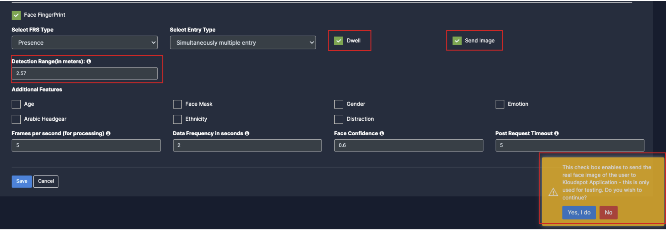
You can enable dwell time as per the requirement. (ex: enable if the camera is for main gate.)
You can enable Send Image for all the faces for testing purpose.
You can also select the Detection Range(in meters) as per the camera and gate distance.
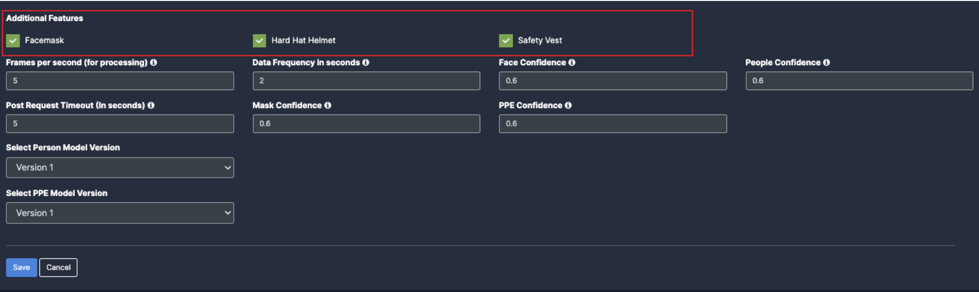
5. Additional Features: -
Age: Once you enable the checkbox of Age, their respective dropdowns will be added below for the respective feature detection.
Face mask: Once you enable the checkbox of Face mask, their respective dropdowns will be added below for the respective feature detection.
Gender: Once you enable the checkbox of Gender, their respective dropdowns will be added below for the respective feature detection.
Emotion: Once you enable the checkbox of Emotion, their respective dropdowns will be added below for the respective feature detection.
Arabic headgear: Once you enable the checkbox of Arabic headgear, their respective dropdowns will be added below for the respective feature detection.
Ethnicity: Once you enable the checkbox of Ethnicity, their respective dropdowns will be added below for the respective feature detection.
Distraction: Once you enable the checkbox of Distraction, their respective dropdowns will be added below for the respective feature detection.
Draw ROI (region of interest) on the camera frame.
ROI in camera frames can help to improve efficiency, accuracy, and reduce storage requirements.
ROI must be added if kiosk mode is enabled. Otherwise, it is optional. If ROI is not added, the model will detect the entire frame.
For face detection, ROI can be drawn in two ways.
Using the polygon tool
Using the rectangle tool.
Draw ROI using the Polygon tool.
Click on the Polygon tool button from the camera frame.
Then connect the dots and draw the polygon in the space where you want to draw the ROI. It should have more than 2 points.
9. After drawing, click the Finish button to complete the drawing.
8. Enter the zone name in the popup window that opens and click the Save button.
New ROI zone added successfully.
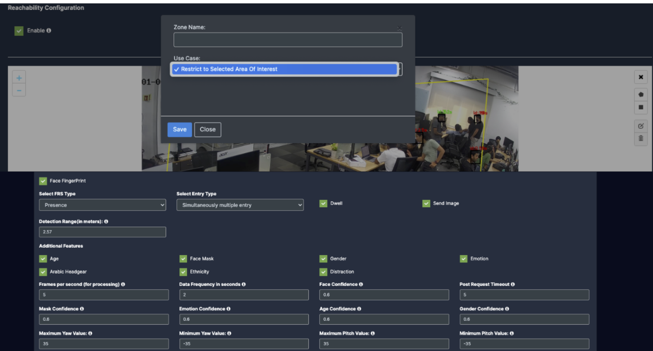
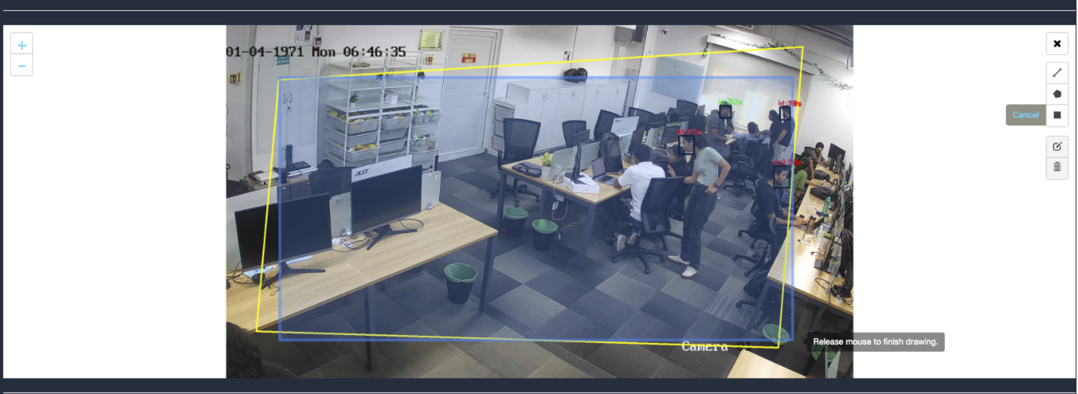
Draw ROI using the rectangle tool.
Click on the Rectangle tool button from the camera frame.
Then draw the rectangle where you want to focus the camera.
8. Then enter the zone name and select Restrict to selected area of interest option from the dropdown list and click the Save button.
Detection will only happen when people enter this zone.
With this ROI you can achieve the below Features:
Face Fingerprint
Additional Features
Once the Use case Configuration is done, click on save.
Your Camera is configured for face monitoring.
Update/ sync Configuration:
Once you perform any change in the controller or update any features/ use cases for camera you need to sync it.
There are 2 types of syncing process:
Sync the configurations
Update the Configurations
Click on sync configuration to restart the complete system syncing process. Basically for the initial camera setup and while any controller configuration update. (It will restart the docker and sync all the performed changes)
Click on the update configuration to recent changes in the system without any downtime. (General configuration sync)
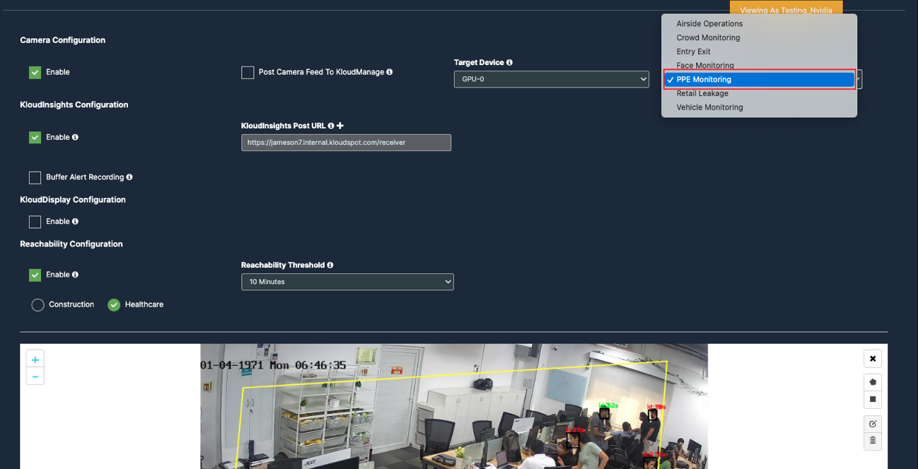
PPE Monitoring
Before you begin configuring the use cases, you should first configure the camera’s general configuration. Refer to the General Camera Configuration section for instructions.
Then, select the PPE Monitoring from the dropdown list
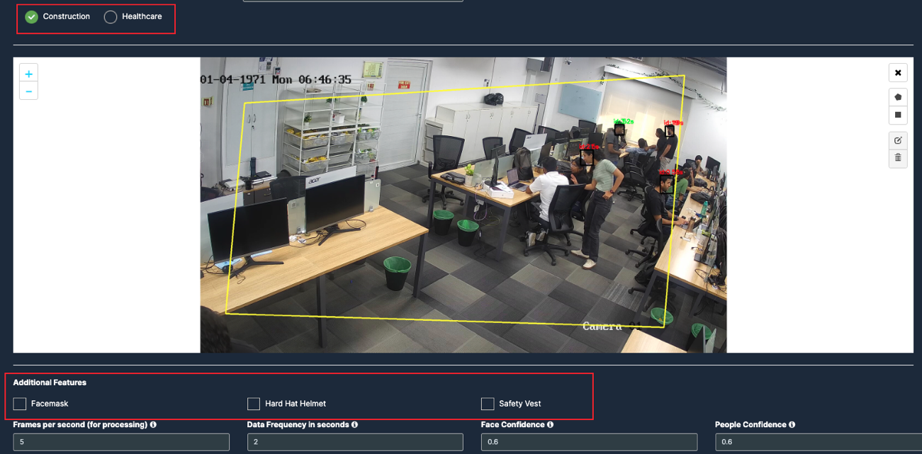
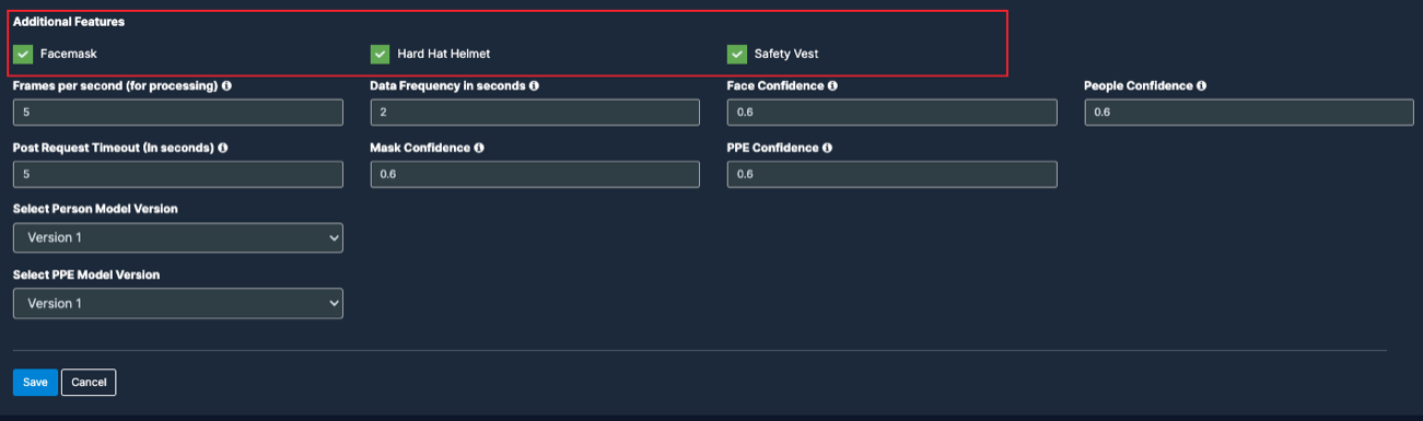
6. There will be checkboxes for Construction and Healthcare. Selecting either checkbox will display the corresponding dropdown options below.
7. Choose construction, Scroll down and choose your preferred use cases. You can choose multiple Features.
8. Now Choose Healthcare, scroll down and choose your preferred use cases. You can choose multiple Features.
Draw ROI (region of interest) on the camera frame.
ROI in camera frames can help to improve efficiency, accuracy, and reduce storage requirements.
ROI must be added if kiosk mode is enabled. Otherwise, it is optional. If ROI is not added, the model will detect the entire frame.
For face detection, ROI can be drawn in two ways.
Using the polygon tool
Using the rectangle tool.
Draw ROI using the Polygon tool.
Click on the Polygon tool button from the camera frame.
Then connect the dots and draw the polygon in the space where you want to draw the ROI. It should have more than 2 points.
15. After drawing, click the Finish button to complete the drawing.
8. Enter the zone name in the popup window that opens and click the Save button.
9. New ROI zone added successfully.
Draw ROI using the rectangle tool.
Click on the Rectangle tool button from the camera frame.
Then draw the rectangle where you want to focus the camera.
Then enter the zone name and select Restrict to selected area of interest option from the dropdown list and click the Save button.
9. Detection will only happen when people enter this zone.
10. With this ROI you can achieve the below Features:
All Additional Features
Once the Use case Configuration is done, click on save.
Your Camera is configured for PPE monitoring.
Update/ sync Configuration:
Once you perform any change in the controller or update any features/ use cases for camera you need to sync it.
There are 2 types of syncing process:
Sync the configurations
Update the Configurations
Click on sync configuration to restart the complete system syncing process. Basically for the initial camera setup and while any controller configuration update. (It will restart the docker and sync all the performed changes)
4. Click on the update configuration to recent changes in the system without any downtime. (General configuration sync)
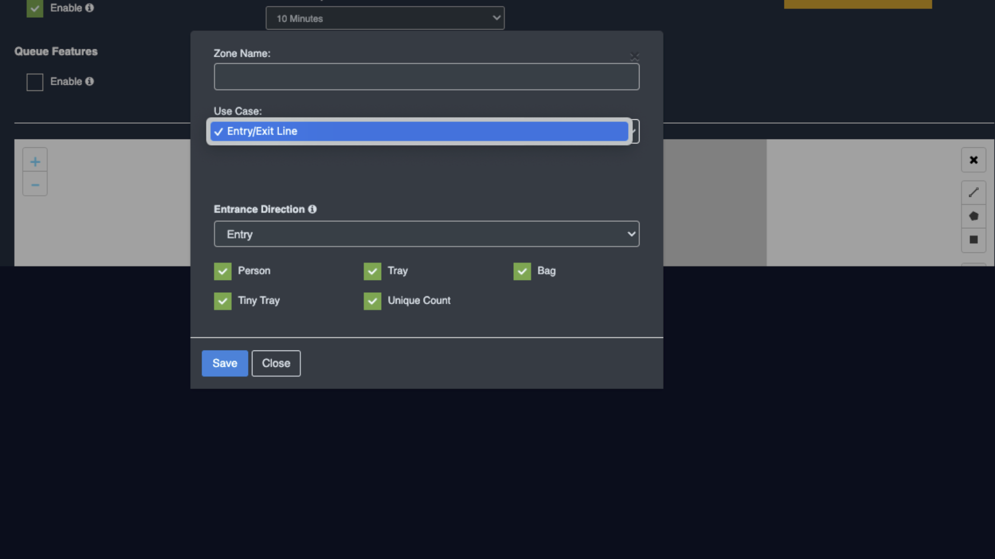
Entry/Exit Count Configuration
Before you begin configuring the use cases, you should first configure the camera’s general configuration. Refer to the General Camera Configuration section for instructions.
Then, select the Entry/ Exit from the dropdown list
Scroll down and choose your preferred use cases. You can choose multiple Features.
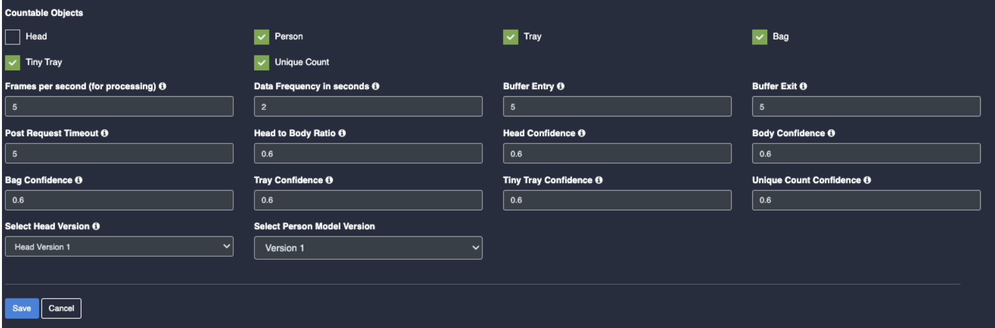
Countable Objects: (Physical items or entities that can be individually identified and counted)
Head: Enable the checkbox of Head as per your feature requirement.
Person: Once you enable the checkbox of Face mask, their respective dropdowns and Unique count checkbox will be added below for the respective feature detection.
Tray: Enable the checkbox of Tray as per your feature requirement for the respective feature detection.
Bag: Enable the checkbox of Bag as per your feature requirement for the respective feature detection.
Tiny Tray: Enable the checkbox of Tiny Tray as per your feature requirement for the respective feature detection.
Unique Count: Enable the checkbox of Unique Count as per your feature requirement
Draw ROI (region of interest) on the camera frame.
ROI in camera frames can help to improve efficiency, accuracy, and reduce storage requirements.
ROI must be added if kiosk mode is enabled. Otherwise, it is optional. If ROI is not added, the model will detect the entire frame.
For face detection, ROI can be drawn in two ways.
Using the Line
Using the polygon tool
Using the rectangle tool.
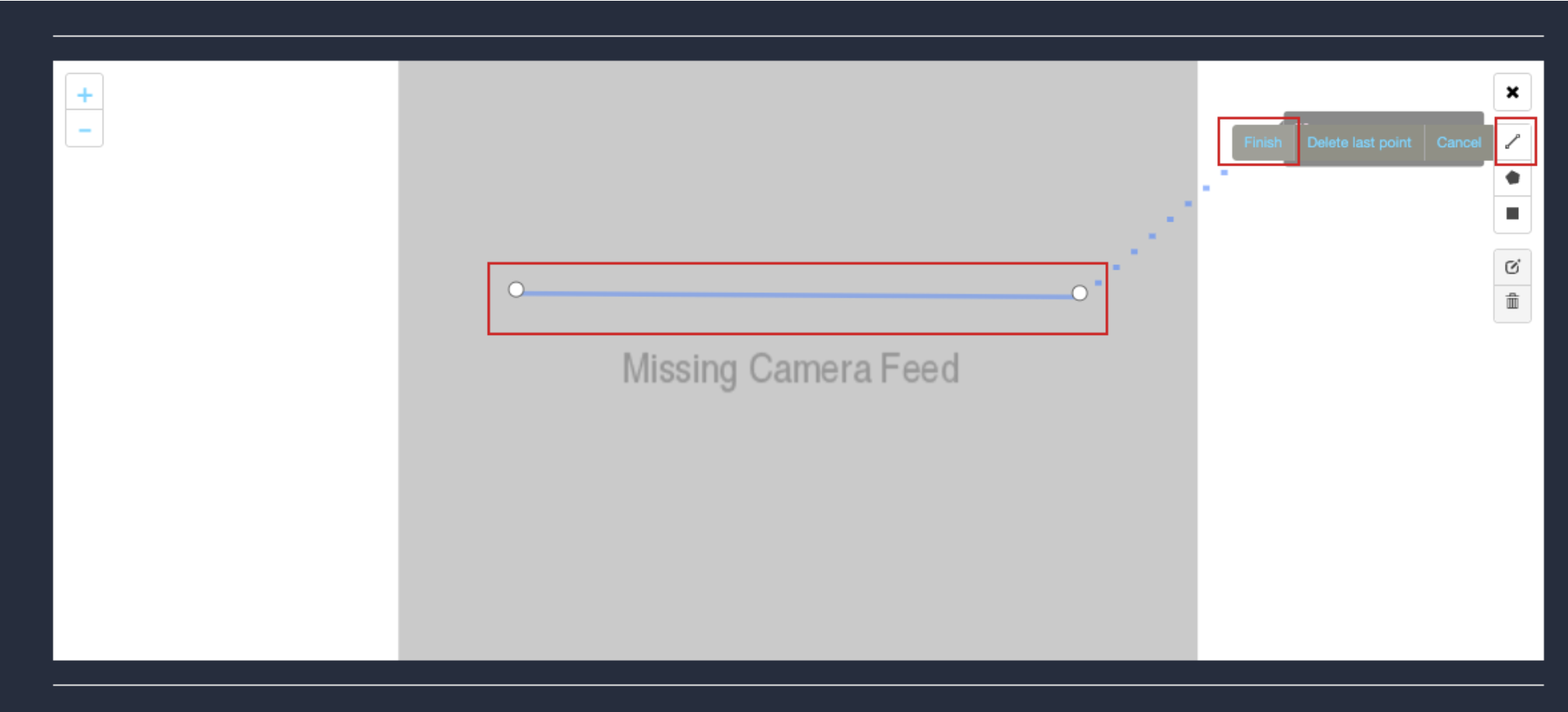
Draw ROI using the line tool.
Click on the Line tool button from the camera frame.
Then draw a straight line on the camera feed.
After drawing, click the Finish button to complete the drawing.
Enter the zone name in the popup window that opens, select the features you want to detect while entry or exit.
After selecting click the Save button.
New ROI zone added successfully
Draw ROI using the Polygon tool.
Click on the Polygon tool button from the camera frame.
Then connect the dots and draw the polygon in the space where you want to draw the ROI. It should have more than 2 points.
After drawing, click the Finish button to complete the drawing.
Enter the zone name in the popup window that opens and click the Save button.
New ROI zone added successfully.
Draw ROI using the rectangle tool.
Click on the Rectangle tool button from the camera frame.
Then draw the rectangle where you want to focus the camera.
13. Then enter the zone name and select Restrict to selected area of interest option from the dropdown list and click the Save button.
Detection will only happen when people enter this zone.
With this ROI you can achieve the below Features:
Countable Objects
Once the Use case Configuration is done, click on save.
Your Camera is configured for Entry/Exit.
Update/ sync Configuration:
Once you perform any change in the controller or update any features/ use cases for camera you need to sync it.
There are 2 types of syncing process:
Sync the configurations
Update the Configurations
Click on sync configuration to restart the complete system syncing process. Basically for the initial camera setup and while any controller configuration update. (It will restart the docker and sync all the performed changes)
Click on the update configuration to recent changes in the system without any downtime. (General configuration sync)
Retail Leakage(RLCC)
Before you begin configuring the use cases, you should first configure the camera’s general configuration. Refer to the General Camera Configuration section for instructions.
Then, select the Retail Leakage from the dropdown list
Scroll down and choose your preferred use cases. You can choose multiple Features.
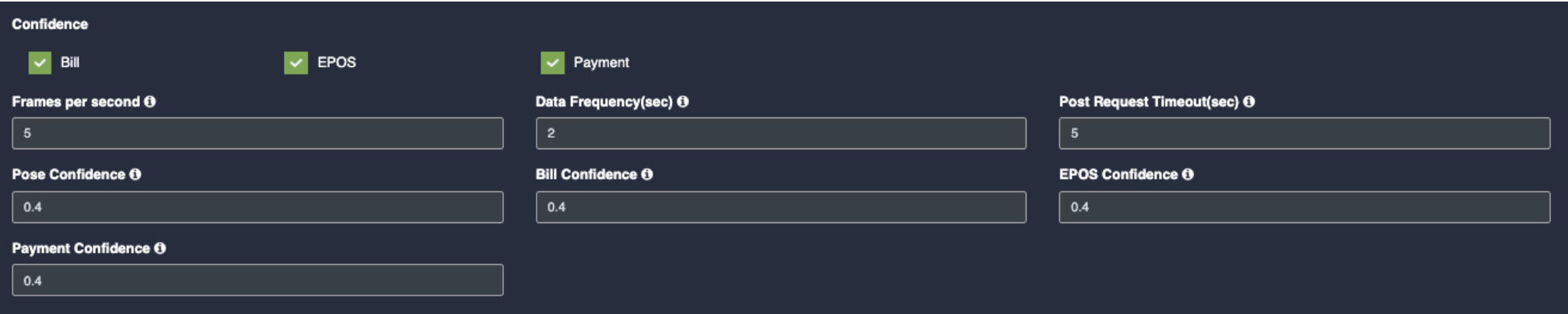
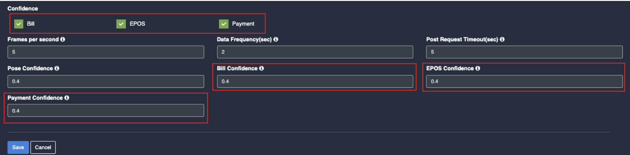
Confidence: (certainty that a detected object, person or action is correctly identified)
Bill: Once you click on the check box of Bill, their respective dropdowns will be added below for the respective feature detection.
EPOS: Once you click on the check box of EPOS, their respective dropdowns will be added below for the respective feature detection.
Payment: Once you click on the check box of payment, their respective dropdowns will be added below for the respective feature detection.
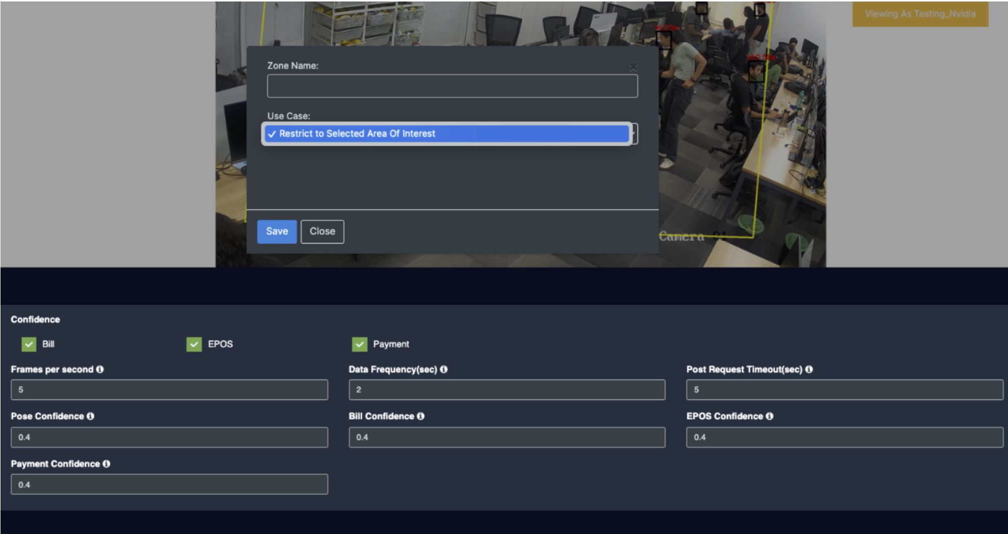
Draw ROI (region of interest) on the camera frame.
ROI in camera frames can help to improve efficiency, accuracy, and reduce storage requirements.
ROI must be added if kiosk mode is enabled. Otherwise, it is optional. If ROI is not added, the model will detect the entire frame.
For face detection, ROI can be drawn in two ways.
Using the polygon tool
Using the rectangle tool.
Draw ROI using the Polygon tool.
Click on the Polygon tool button from the camera frame.
Then connect the dots and draw the polygon in the space where you want to draw the ROI. It should have more than 2 points.
After drawing, click the Finish button to complete the drawing.
Enter the zone name in the popup window that opens and click the Save button.
New ROI zone added successfully.
Draw ROI using the rectangle tool.
Click on the Rectangle tool button from the camera frame.
Then draw the rectangle where you want to focus the camera.
Then enter the zone name and select Restrict to selected area of interest option from the dropdown list and click the Save button.
Detection will only happen when people enter this zone.
With this ROI you can achieve the below Features:
All Confidence features
Once the Use case Configuration is done, click on save.
Your Camera is configured for RLCC.
Update/ sync Configuration:
Once you perform any change in the controller or update any features/ use cases for camera you need to sync it.
There are 2 types of syncing process:
Sync the configurations
Update the Configurations
Click on sync configuration to restart the complete system syncing process. Basically for the initial camera setup and while any controller configuration update. (It will restart the docker and sync all the performed changes)
4. Click on the update configuration to recent changes in the system without any downtime. (General configuration sync)
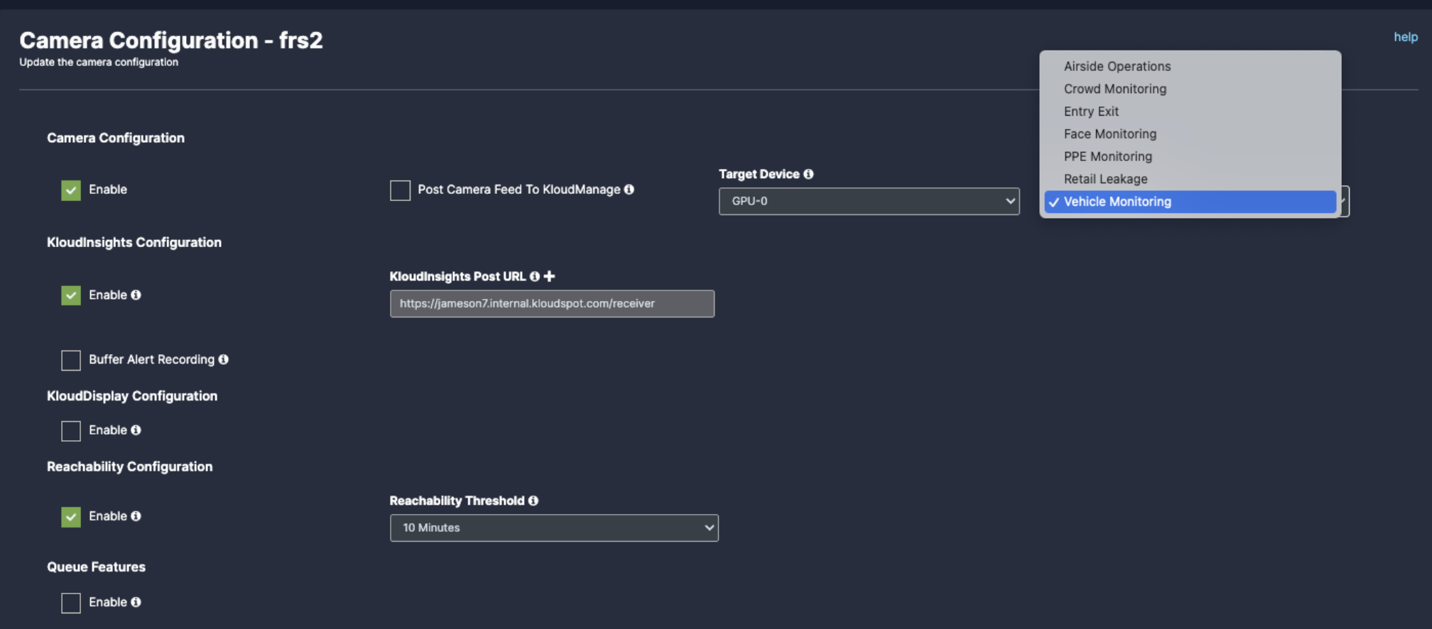
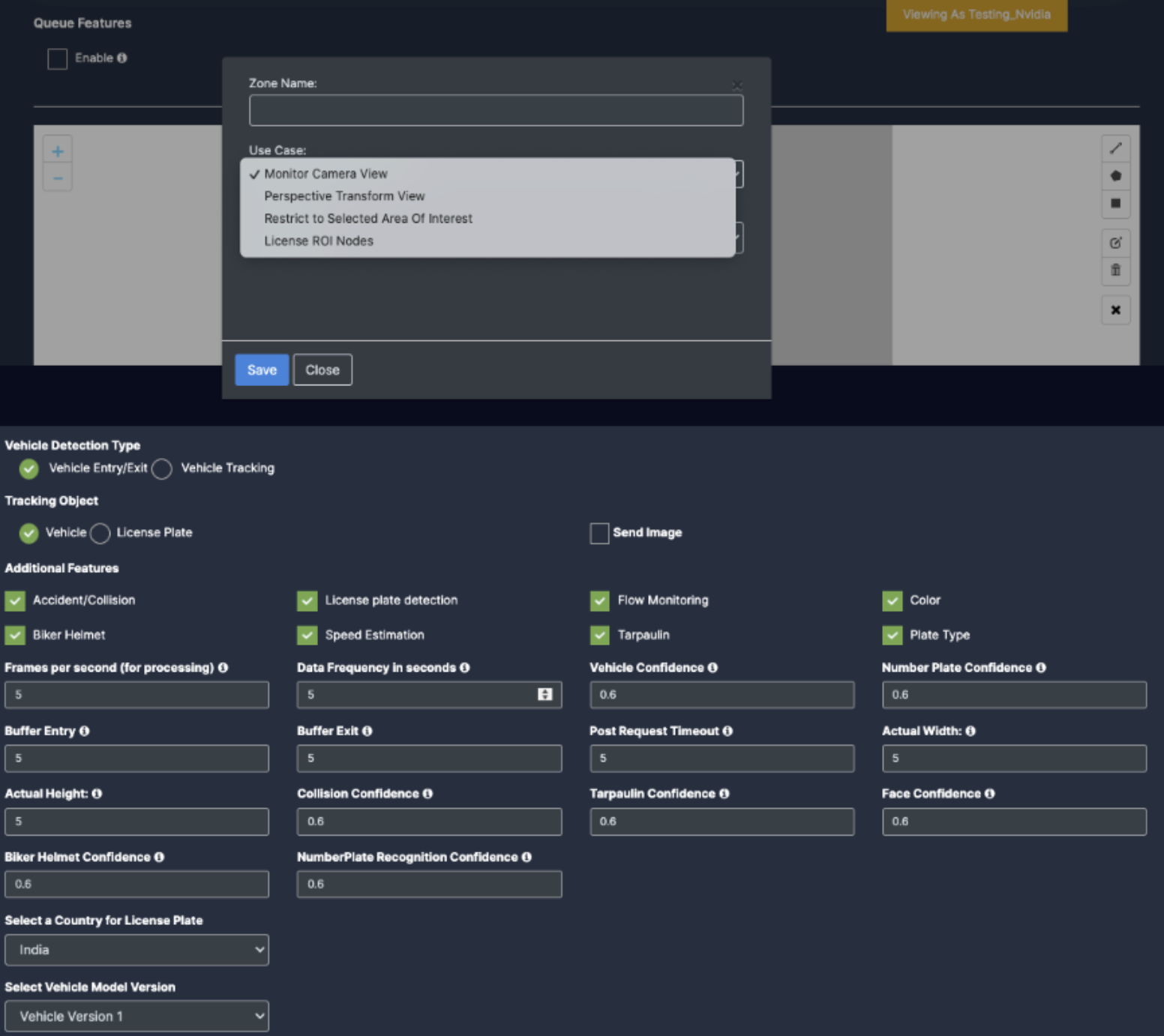
Vehicle Monitoring
Before you begin configuring the use cases, you should first configure the camera’s general configuration. Refer to the General Camera Configuration section for instructions.
Then, select the Vehicle monitoring from the dropdown list
3. Scroll down and choose your preferred use cases. You can choose multiple Features.
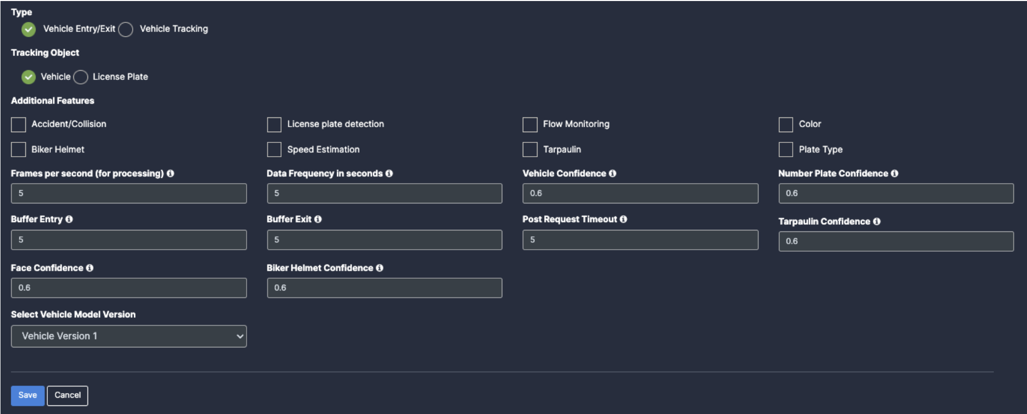
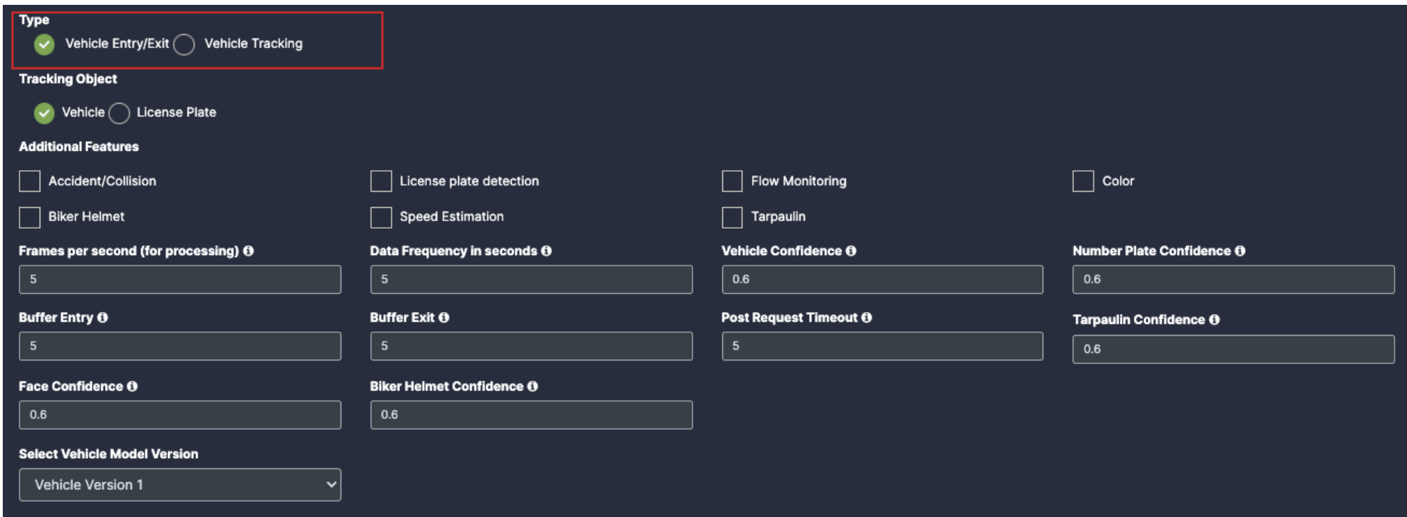
4. In Vehicle Monitoring there are 2 types of detection
Vehicle Entry/Exit
Vehicle Tracking
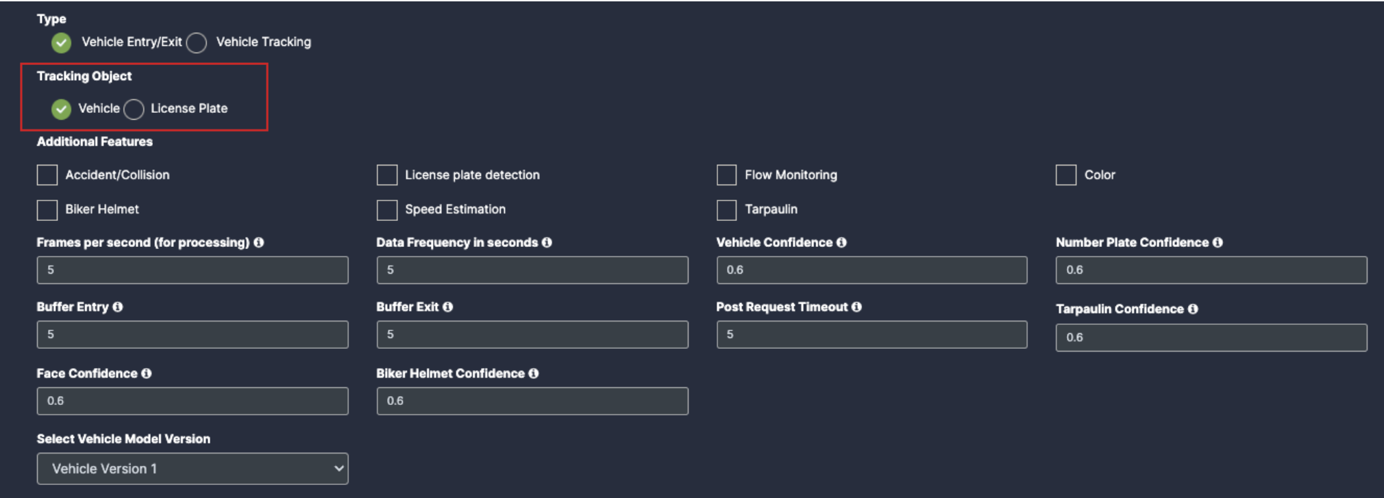
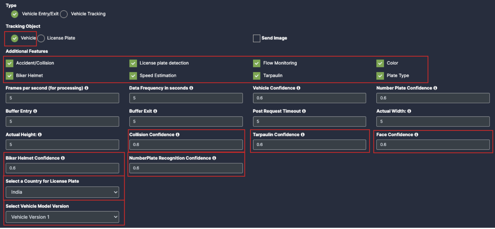
Vehicle Entry/Exit have 2 type of tracking features, which is Vehicle and License Plate.
6. Selecting any of the type will show the respective check boxes and dropdown below.
7. Selecting Vehicle:
Accident/Collision: Once you click on the check box of Accident/Collision, their respective dropdowns will be added below for the respective feature detection.
License plate detection: Once you click on the check box of License plate detection, their respective dropdowns and Plate type check box will be added below for the respective feature detection.
Flow Monitoring: Once you click on the check box of Flow Monitoring, their respective dropdowns will be added below for the respective feature detection.
Color: Once you click on the check box of Color, their respective dropdowns will be added below for the respective feature detection.
Biker Helmet: Once you click on the check box of Biker Helmet, their respective dropdowns will be added below for the respective feature detection.
Speed Estimation: Once you click on the check box of Speed Estimation, their respective dropdowns will be added below for the respective feature detection.
Tarpaulin: Once you click on the check box of Tarpaulin, their respective dropdowns will be added below for the respective feature detection.
Plate type: Enable the check box of plate type for respective detection.
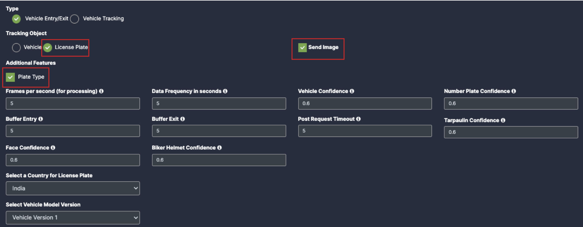
8. Selecting License Plate:
Plate Type: To detect the License Plate and its Type.
Accident/Collision: Once you click on the check box of Accident/Collision, their respective dropdowns will be added below for the respective feature detection.
License plate detection: Once you click on the check box of License plate detection, their respective dropdowns will be added below for the respective feature detection.
Flow Monitoring: Once you click on the check box of Flow Monitoring, their respective dropdowns will be added below for the respective feature detection.
Color: Once you click on the check box of Color, their respective dropdowns will be added below for the respective feature detection.
Biker Helmet: Once you click on the check box of Biker Helmet, their respective dropdowns will be added below for the respective feature detection.
Speed Estimation: Once you click on the check box of Speed Estimation, their respective dropdowns will be added below for the respective feature detection.
Tarpaulin: Once you click on the check box of Tarpaulin, their respective dropdowns will be added below for the respective feature detection.
Plate Type: Enable the check box of plate type for the respective detection.
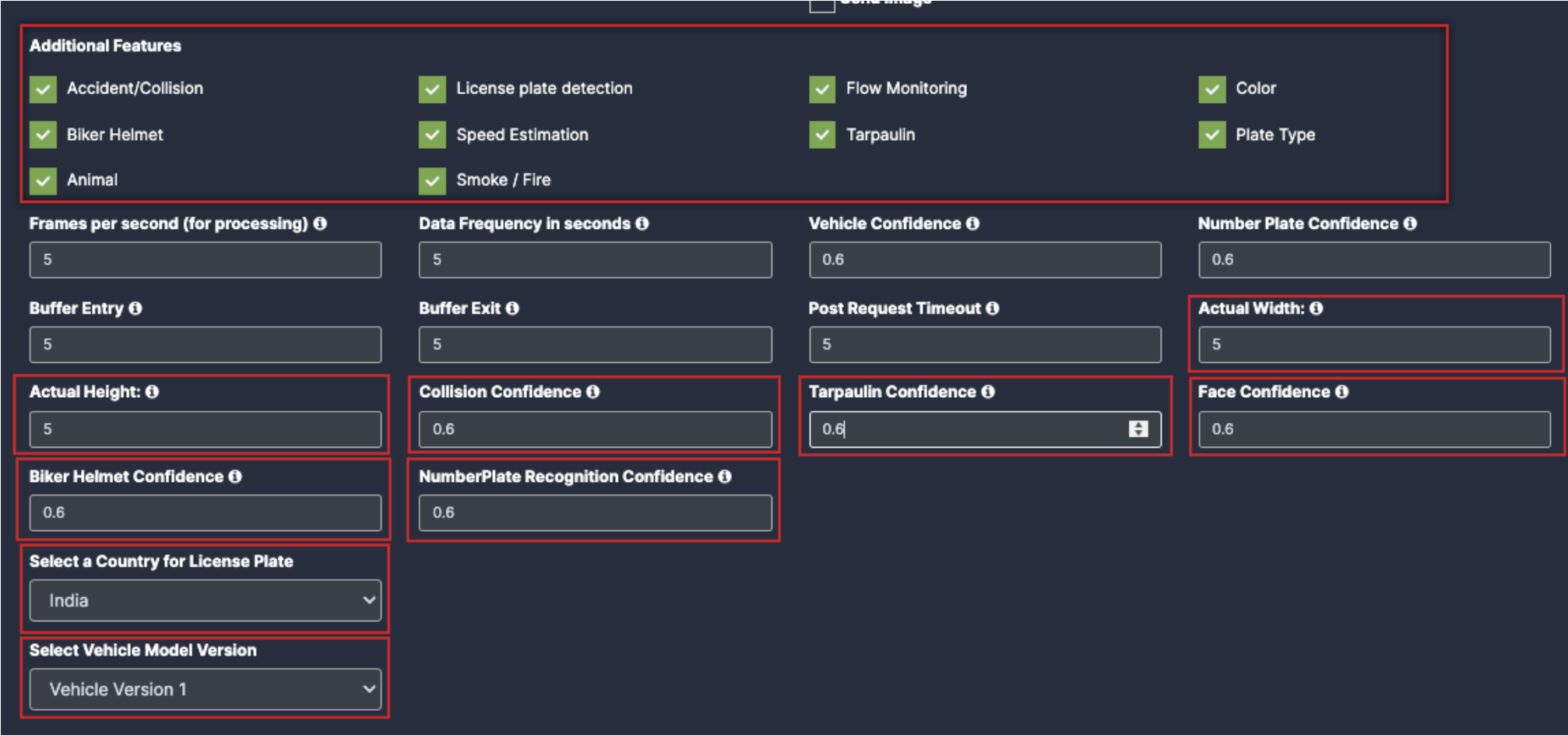
Animal: Enable the check box of Animal for the respective detection
Smoke/Fire: Enable the check box of Smoke/Fire for the respective detection.
Draw ROI (region of interest) on the camera frame.
ROI in camera frames can help to improve efficiency, accuracy, and reduce storage requirements.
ROI must be added if kiosk mode is enabled. Otherwise, it is optional. If ROI is not added, the model will detect the entire frame.
For face detection, ROI can be drawn in two ways.
Using the polygon tool
Using the rectangle tool.
Draw ROI using the Polygon tool.
Click on the Polygon tool button from the camera frame.
Then connect the dots and draw the polygon in the space where you want to draw the ROI. It should have more than 2 points.
12. After drawing, click the Finish button to complete the drawing.
11. Enter the zone name in the popup window that opens and click the Save button.
12. New ROI zone added successfully.
Draw ROI using the rectangle tool.
Click on the Rectangle tool button from the camera frame.
Then draw the rectangle where you want to focus the camera.
23. Then enter the zone name and select Restrict to selected area of interest option from the dropdown list and click the Save button.
24. Detection will only happen when people enter this zone.
25. With this ROI you can achieve the below Features:
All Vehicle Detection
Tracking Object
Additional Features
Once the Use case Configuration is done, click on save.
Your Camera is configured for Vehicle Monitoring.
Update/ sync Configuration:
Once you perform any change in the controller or update any features/ use cases for camera you need to sync it.
There are 2 types of syncing process:
Sync the configurations
Update the Configurations
3. Click on sync configuration to restart the complete system syncing process. Basically for the initial camera setup and while any controller configuration update. (It will restart the docker and sync all the performed changes)
Click on the update configuration to recent changes in the system without any downtime. (General configuration sync)
Airside Operations
Before you begin configuring the use cases, you should first configure the camera’s general configuration. Refer to the General Camera Configuration section for instructions.
Then, select the Airside operations from the dropdown list
Scroll down and you will see the 2 type of detection which is:
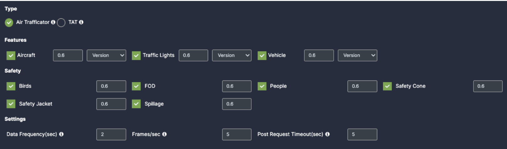
Air Trafficator
TAT(Turnaround Time)
Select Air trafficator, scroll down and choose your preferred use cases. You can choose multiple Features.
5. Features:
Aircraft: Once you enable the checkbox of Aircraft, you will get respective confidence and version dropdown.
Traffic Lights: Once you enable the checkbox of Traffic Lights, you will get respective confidence and version dropdown.
Vehicle: Once you enable the checkbox of Vehicle, you will get respective confidence and version dropdown.
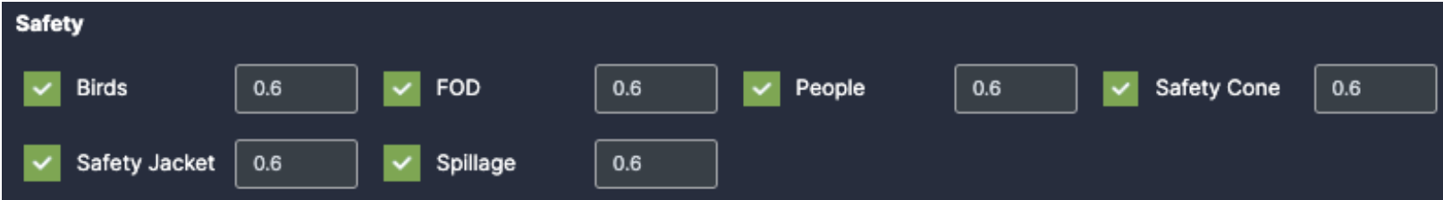
6. Safety:
Birds: Once you enable the checkbox of Birds, you will get respective confidence.
FOD: Once you enable the checkbox of FOD, you will get respective confidence.
People: Once you enable the checkbox of People, you will get respective confidence.
Safety Jacket: Once you enable the checkbox of Safety Jacket, you will get respective confidence.
Spillage: Once you enable the checkbox of Spillage, you will get respective confidence.
7. Settings:
Data Frequency(sec): Fill the setting as per your requirements
Frames/Sec: Fill the setting as per your requirements
Post Request Timeout(sec): Fill the setting as per your requirements
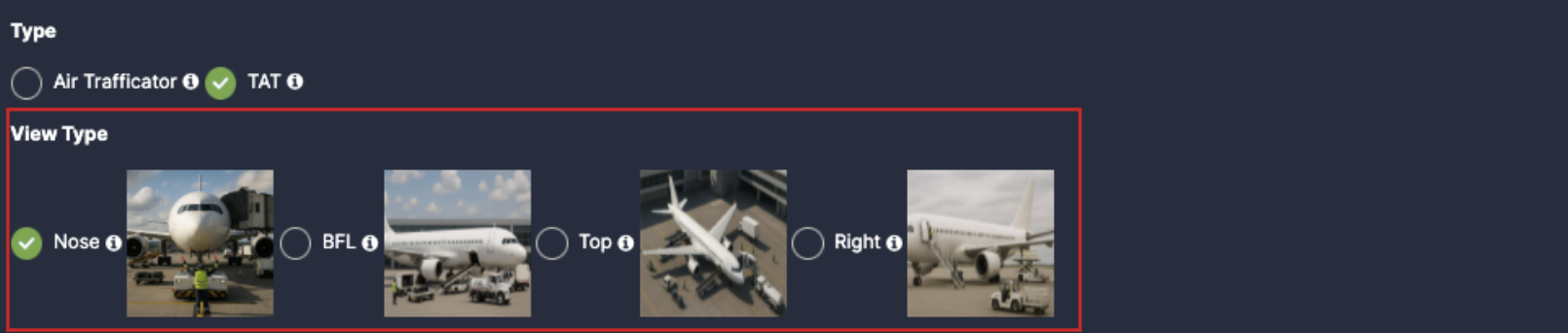
Now, Select TAT and scroll down to choose your preferred use cases. You can choose multiple Features.
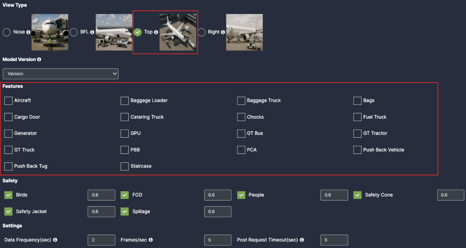
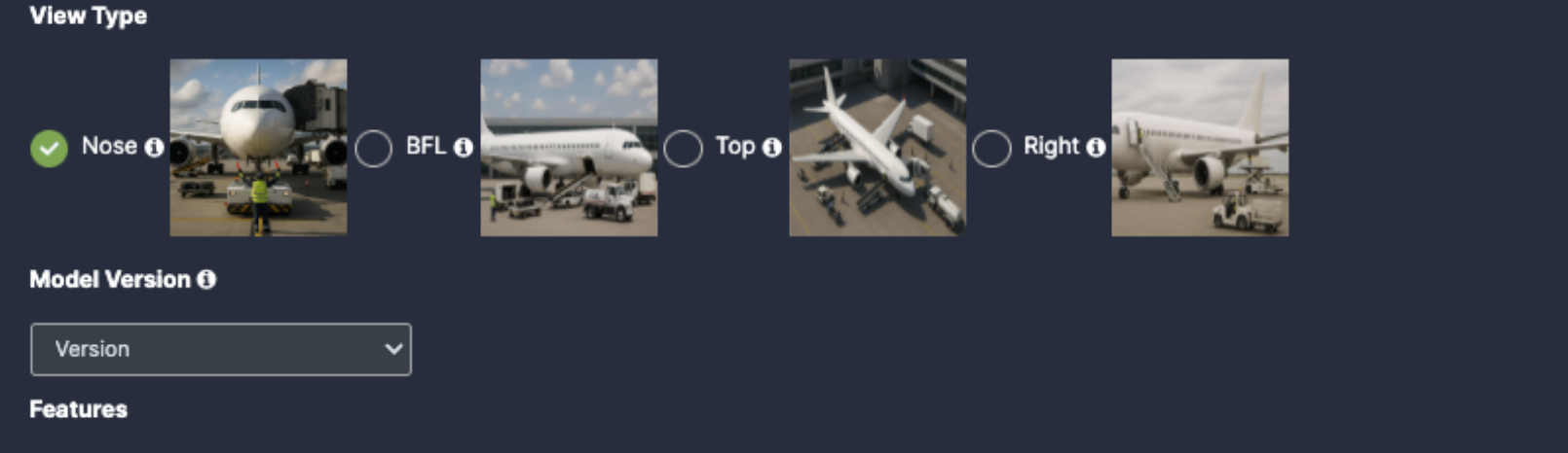
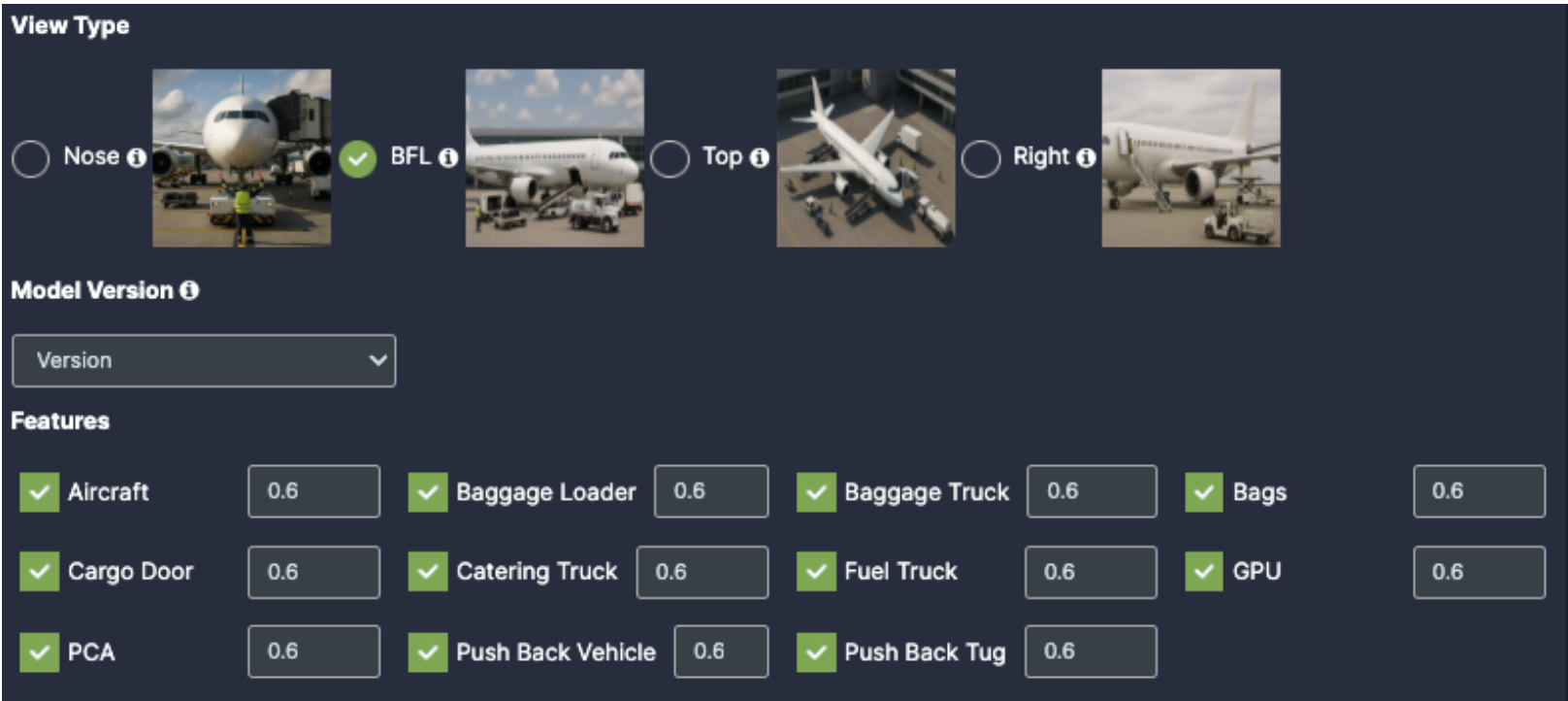
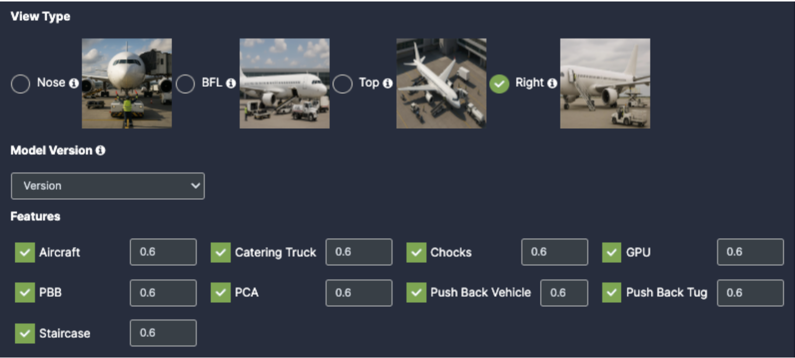
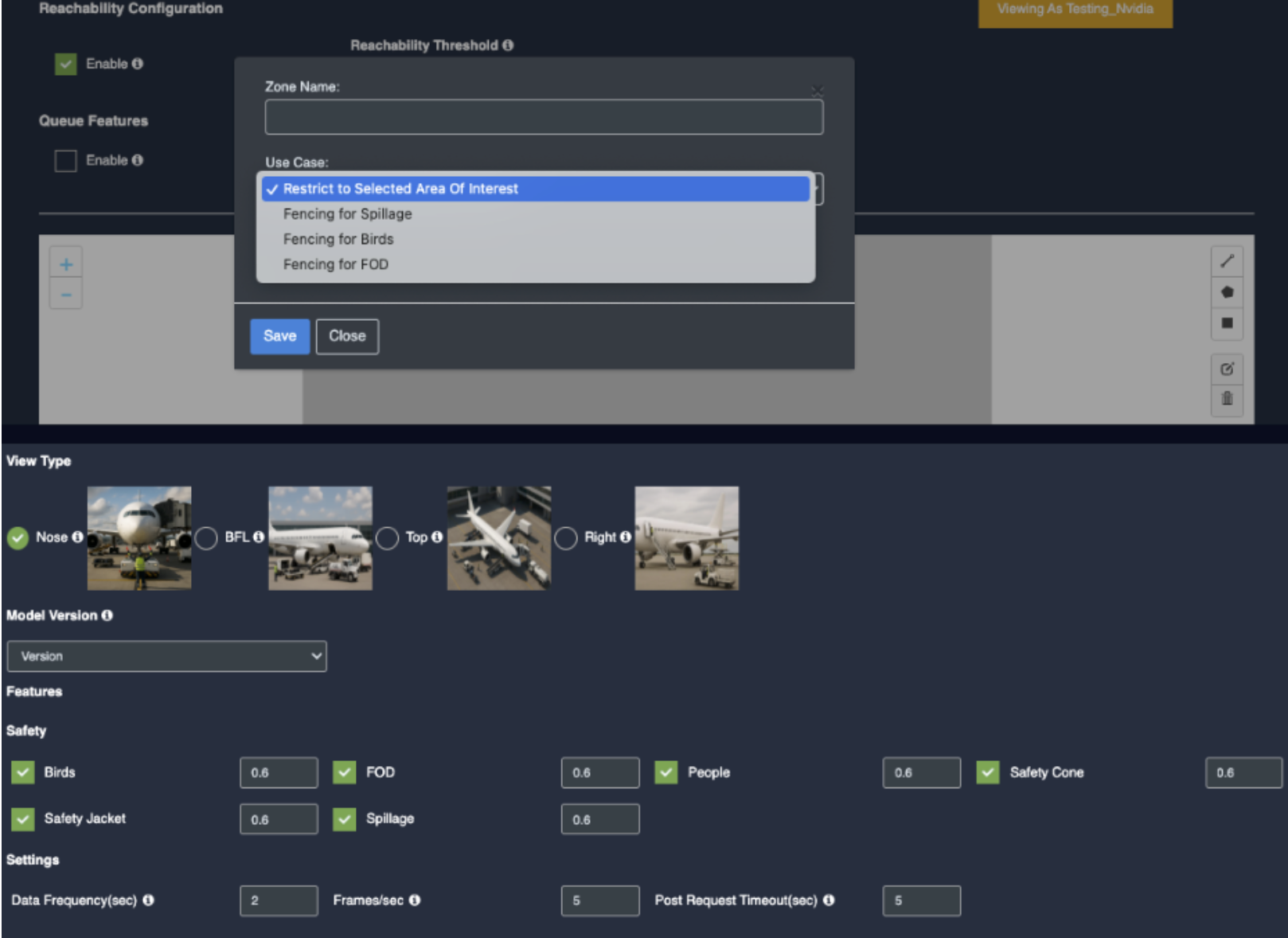
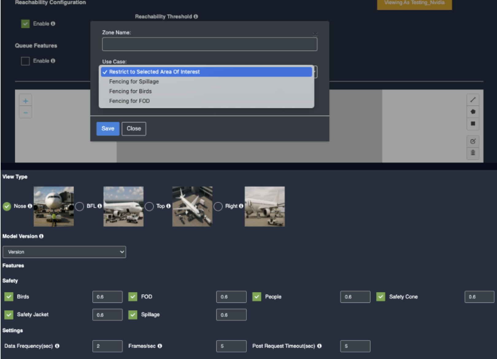
In TAT there is view type which contains 4 options:
Nose: The Camera capture the frontal view of the aircraft, primarily focusing on the nose section.
BFL(Baggage freight loader): The camera provides the clear view of the aircraft’s left side, capturing operations and equipment positioned on this side.
TOP: The Camera is mounted overhead to provide a bird’s-eye view of the aircraft and its surroundings. This offers comprehensive coverage of all ground activities around the aircraft.
Right: This perspective covers the right side of the aircraft, suitable for monitoring activities or equipment on that side.
Selecting each of the view type will provide the respective checkboxes below:
11. Select view type: Nose
Model Version: Select the model version as per your requirement.
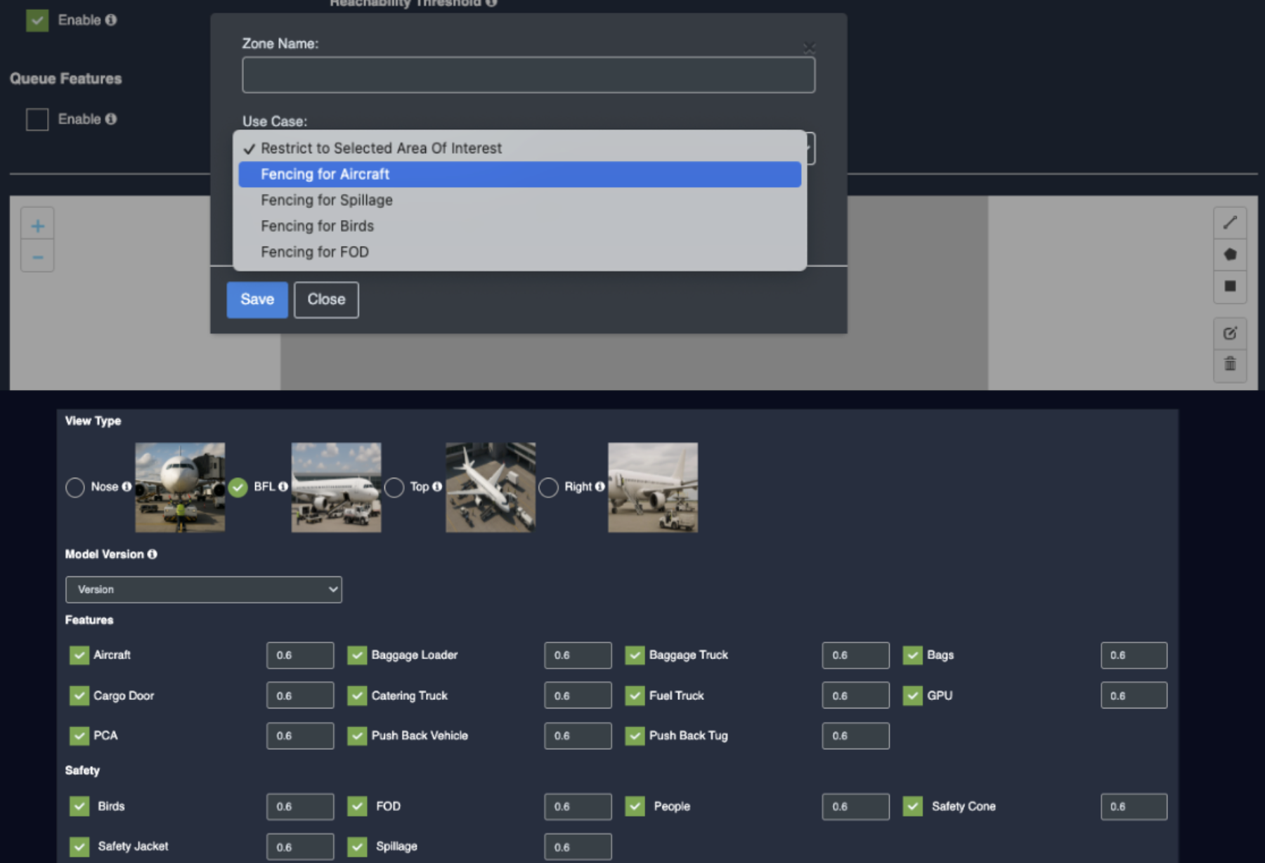
Select view type: BFL(Baggage freight loader)
Aircraft: Once you enable the checkbox of Aircraft, you will get respective confidence to fill
Baggage Loader: Once you enable the checkbox of Baggage Loader, you will get respective confidence to fill
Baggage Truck: Once you enable the checkbox of Baggage Truck, you will get respective confidence to fill
Bags: Once you enable the checkbox of Bags, you will get respective confidence to fill
Cargo Door: Once you enable the checkbox of Cargo Door, you will get respective confidence to fill
Catering Truck: Once you enable the checkbox of Catering Truck, you will get respective confidence to fill
Fuel Truck: Once you enable the checkbox of Fuel Truck, you will get respective confidence to fill
GPU(Ground Power Unit): Once you enable the checkbox of GPU, you will get respective confidence to fill
PCA(Pre conditioned air): Once you enable the checkbox of PCA, you will get respective confidence to fill
Push Back Vehicle: Once you enable the checkbox of Push Back Vehicle, you will get respective confidence to fill
Push Back Tug: Once you enable the checkbox of Push Back Tug, you will get respective confidence to fill
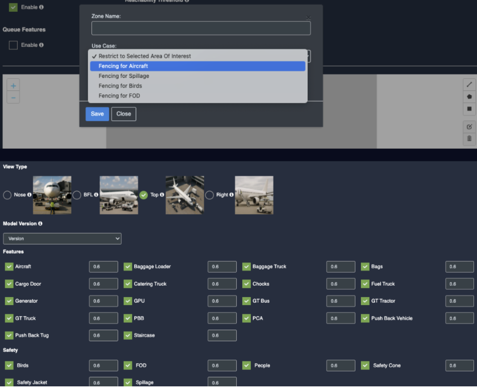
Select view type: TOP
Aircraft: Once you enable the checkbox of Aircraft, you will get respective confidence to fill
Baggage Loader: Once you enable the checkbox of Baggage Loader, you will get respective confidence to fill
Baggage Truck: Once you enable the checkbox of Baggage Truck, you will get respective confidence to fill
Bags: Once you enable the checkbox of Bags, you will get respective confidence to fill
Cargo Door: Once you enable the checkbox of Cargo Door, you will get respective confidence to fill
Catering Truck: Once you enable the checkbox of Catering Truck, you will get respective confidence to fill
Chocks: Once you enable the checkbox of Chocks, you will get respective confidence to fill
Fuel Truck: Once you enable the checkbox of Fuel Truck, you will get respective confidence to fill
Generator: Once you enable the checkbox of Generator, you will get respective confidence to fill
GPU(Ground Power Unit): Once you enable the checkbox of GPU, you will get respective confidence to fill
GT Bus: Once you enable the checkbox of GT Bus, you will get respective confidence to fill
GT Tractor: Once you enable the checkbox of GT Tractor, you will get respective confidence to fill
GT TRUCK: Once you enable the checkbox of GT TRUCK, you will get respective confidence to fill
PBB(passenger boarding bridge): Once you enable the checkbox of PBB, you will get respective confidence to fill
PCA(Pre conditioned air): Once you enable the checkbox of PCA, you will get respective confidence to fill
Push Back Vehicle: Once you enable the checkbox of Push Back Vehicle, you will get respective confidence to fill
Push Back Tug: Once you enable the checkbox of Push Back Tug, you will get respective confidence to fill
Staircase: Once you enable the checkbox of Staircase, you will get respective confidence to fill
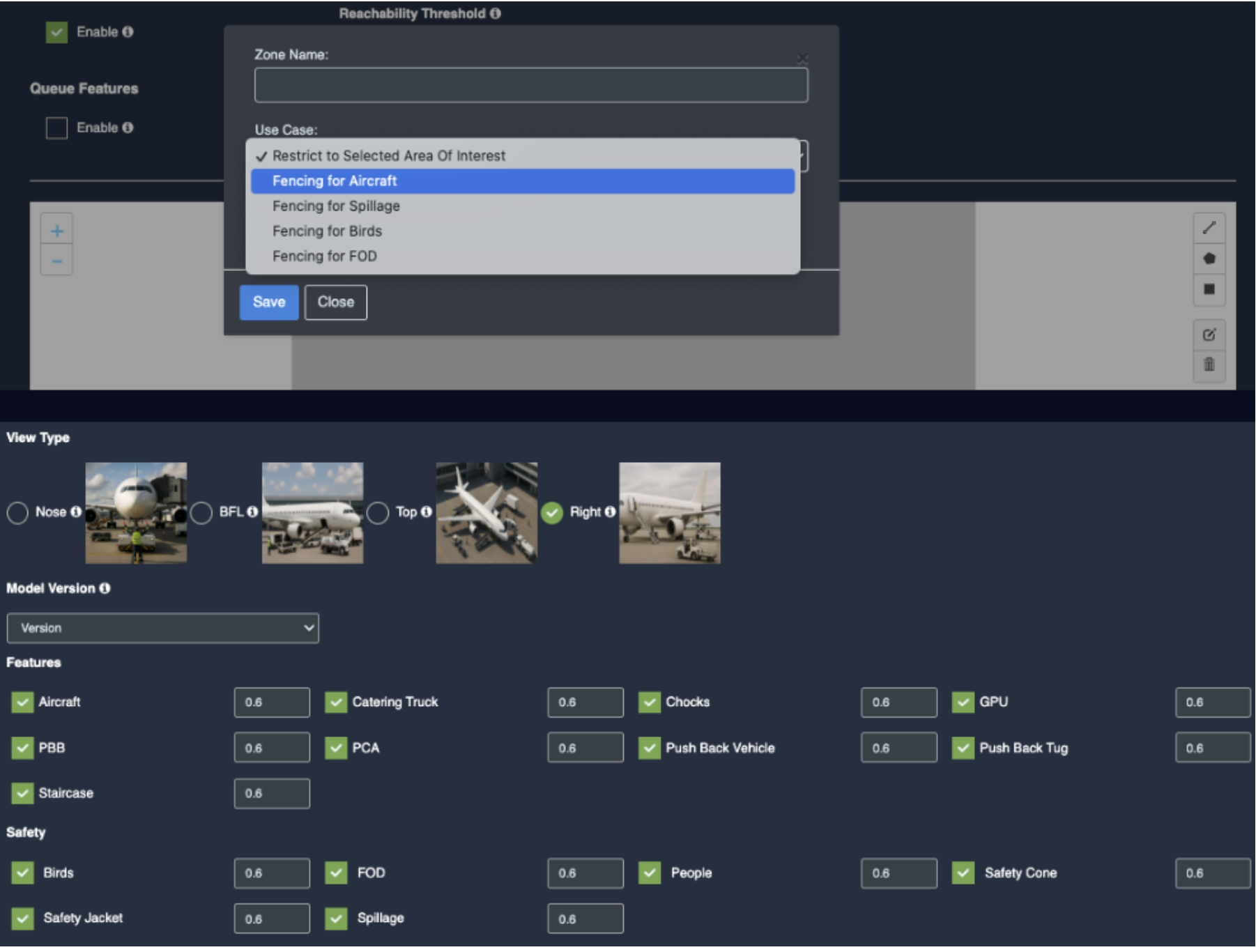
14. Select view type: Right
Aircraft: Once you enable the checkbox of Aircraft, you will get respective confidence to fill
Catering Truck: Once you enable the checkbox of Catering Truck, you will get respective confidence to fill
Chocks: Once you enable the checkbox of Chocks, you will get respective confidence to fill
GPU(Ground Power Unit): Once you enable the checkbox of GPU, you will get respective confidence to fill
PBB(passenger boarding bridge): Once you enable the checkbox of PBB, you will get respective confidence to fill
PCA(Pre conditioned air): Once you enable the checkbox of PCA, you will get respective confidence to fill
Push Back Vehicle: Once you enable the checkbox of Push Back Vehicle, you will get respective confidence to fill
Push Back Tug: Once you enable the checkbox of Push Back Tug, you will get respective confidence to fill
Staircase: Once you enable the checkbox of Staircase, you will get respective confidence to fill
15. Safety(common:
Birds: Once you enable the checkbox of Birds, you will get respective confidence.
FOD: Once you enable the checkbox of FOD, you will get respective confidence.
People: Once you enable the checkbox of People, you will get respective confidence.
Safety Jacket: Once you enable the checkbox of Safety Jacket, you will get respective confidence.
Spillage: Once you enable the checkbox of Spillage, you will get respective confidence.
Setting:
Data Frequency(sec): Fill the setting as per your requirements
Frames/Sec: Fill the setting as per your requirements
Post Request Timeout(sec): Fill the setting as per your requirements
Draw ROI (region of interest) on the camera frame.
ROI in camera frames can help to improve efficiency, accuracy, and reduce storage requirements.
ROI must be added if kiosk mode is enabled. Otherwise, it is optional. If ROI is not added, the model will detect the entire frame.
For face detection, ROI can be drawn in two ways.
Using the polygon tool
cUsing the rectangle tool.
Draw ROI using the Polygon tool (Air Trafficator)
Click on the Polygon tool button from the camera frame.
Then connect the dots and draw the polygon in the space where you want to draw the ROI. It should have more than 2 points.
15. After drawing, click the Finish button to complete the drawing.
Enter the zone name in the popup window that opens and click the Save button.
New ROI zone added successfully.
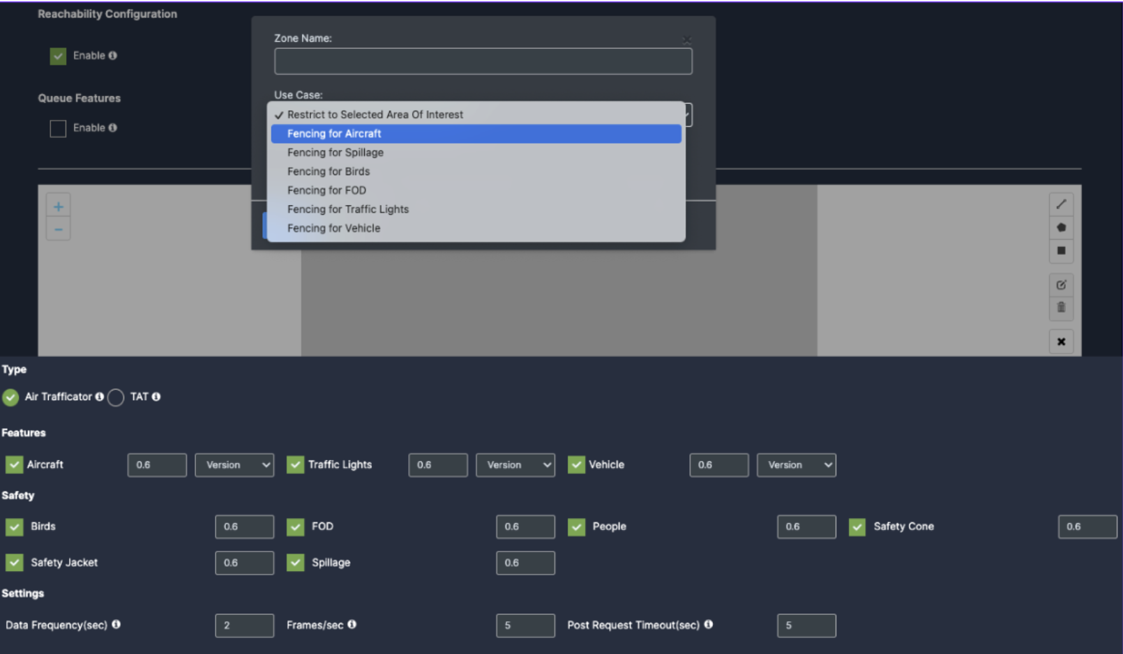
Draw ROI using the rectangle tool(Air Trafficator)
Click on the Rectangle tool button from the camera frame.
Then draw the rectangle where you want to focus the camera.
Then enter the zone name and select Restrict to selected area of interest option from the dropdown list and click the Save button.
Detection will only happen when people enter this zone.
With this ROI you can achieve the below Features:
Countable Objects
Once the Use case Configuration is done, click on save.
TAT:
Draw ROI using the Polygon tool (TAT: Nose view type)
Click on the Polygon tool button from the camera frame.
Then connect the dots and draw the polygon in the space where you want to draw the ROI. It should have more than 2 points.
18. After drawing, click the Finish button to complete the drawing.
15. Enter the zone name in the popup window that opens and click the Save button.
16. New ROI zone added successfully.
Draw ROI using the rectangle tool(TAT: Nose view type)
Click on the Rectangle tool button from the camera frame.
Then draw the rectangle where you want to focus the camera.
32. Then enter the zone name and select Restrict to selected area of interest option from the dropdown list and click the Save button.
Detection will only happen when people enter this zone.
Once the Use case Configuration is done, click on save.
BFL view type:
Draw ROI using the Polygon tool (TAT: BFL view type)
Click on the Polygon tool button from the camera frame.
Then connect the dots and draw the polygon in the space where you want to draw the ROI. It should have more than 2 points.
21. After drawing, click the Finish button to complete the drawing.
17. Enter the zone name in the popup window that opens and click the Save button.
18. New ROI zone added successfully.
Draw ROI using the rectangle tool(TAT: BFL view type)
Click on the Rectangle tool button from the camera frame.
Then draw the rectangle where you want to focus the camera.
Then enter the zone name and select Restrict to selected area of interest option from the dropdown list and click the Save button.
36. Detection will only happen when people enter this zone.
37. Once the Use case Configuration is done, click on save.
TOP view type:
Draw ROI using the Polygon tool (TAT: Top view type)
Click on the Polygon tool button from the camera frame.
Then connect the dots and draw the polygon in the space where you want to draw the ROI. It should have more than 2 points.
After drawing, click the Finish button to complete the drawing.
19. Enter the zone name in the popup window that opens and click the Save button.
20. New ROI zone added successfully.
Draw ROI using the rectangle tool(TAT: Top view type)
Click on the Rectangle tool button from the camera frame.
Then draw the rectangle where you want to focus the camera.
Then enter the zone name and select Restrict to selected area of interest option from the dropdown list and click the Save button.
39. Detection will only happen when people enter this zone.
40. Once the Use case Configuration is done, click on save.
Right view type:
Draw ROI using the Polygon tool (TAT: Right view type)
Click on the Polygon tool button from the camera frame.
Then connect the dots and draw the polygon in the space where you want to draw the ROI. It should have more than 2 points.
27. After drawing, click the Finish button to complete the drawing.
21. Enter the zone name in the popup window that opens and click the Save button.
22. New ROI zone added successfully.
Draw ROI using the rectangle tool(TAT: Right view type)
Click on the Rectangle tool button from the camera frame.
Then draw the rectangle where you want to focus the camera.
Then enter the zone name and select Restrict to selected area of interest option from the dropdown list and click the Save button.
42. Detection will only happen when people enter this zone.
43. Once the Use case Configuration is done, click on save.
44. Your Camera is configured for Airside Monitoring.
Update/ sync Configuration:
Once you perform any change in the controller or update any features/ use cases for camera you need to sync it.
There are 2 types of syncing process:
Sync the configurations
Update the Configurations
Click on sync configuration to restart the complete system syncing process. Basically for the initial camera setup and while any controller configuration update. (It will restart the docker and sync all the performed changes)
Click on the update configuration to recent changes in the system without any downtime. (General configuration sync)
Integrating with KloudInsights
Same as before:
Creating Rules and Notifications
Same as before:
Generating Widgets and Insights
Same as before:
Video Gallery and Playback
Same as before:
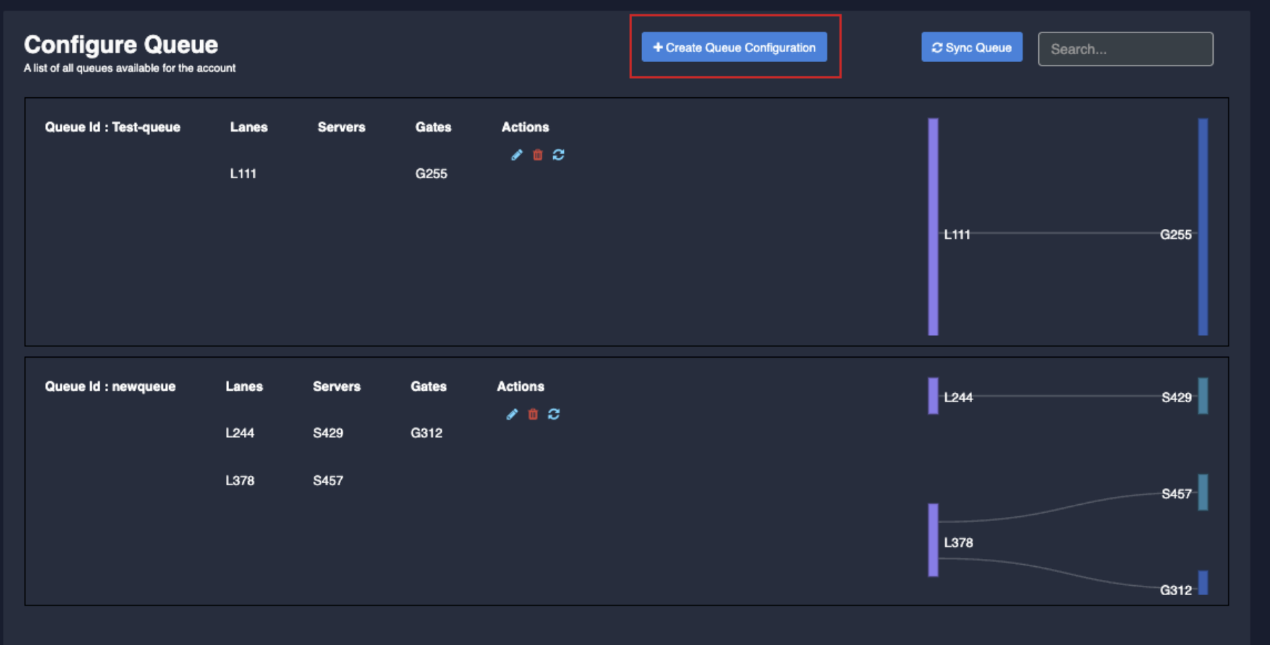
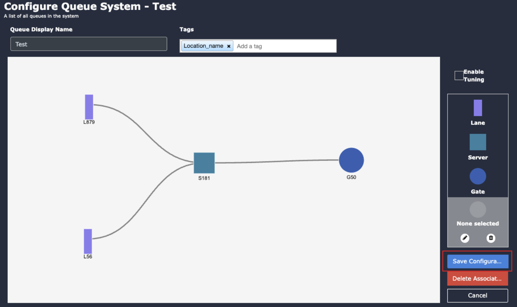
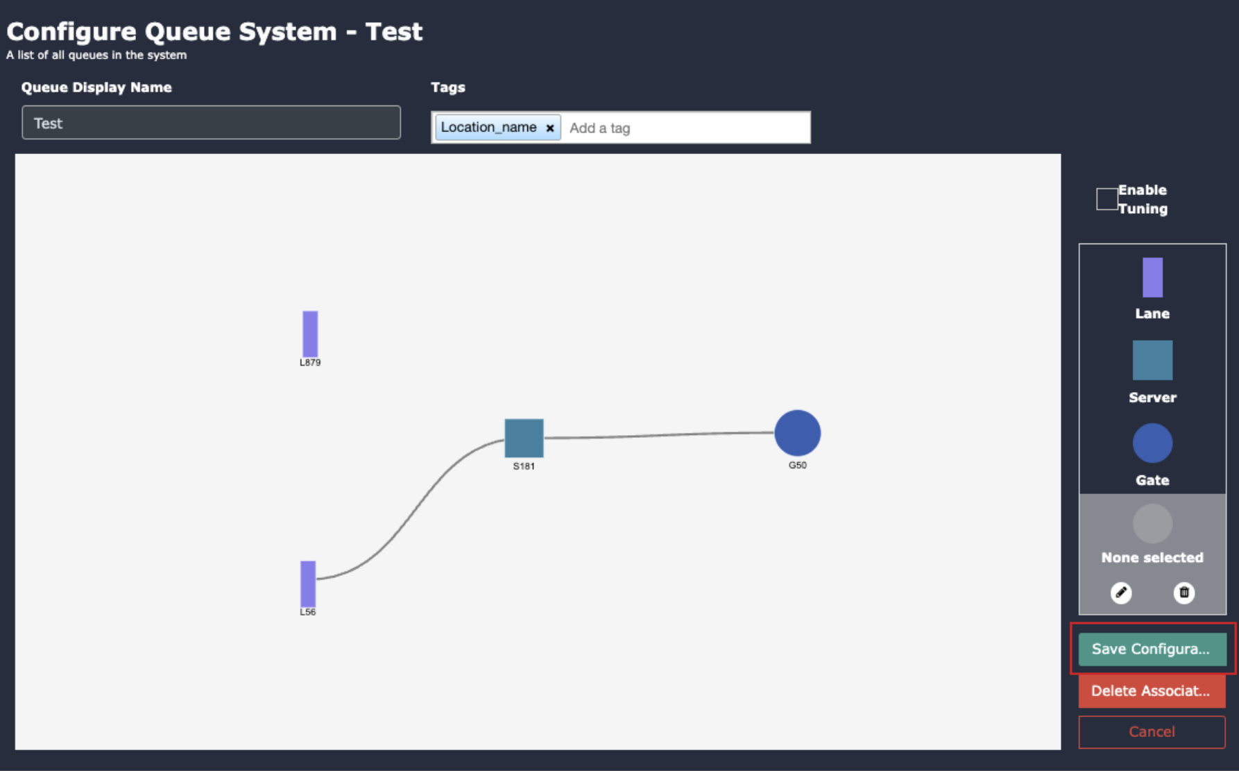
Queue Creation
Go to “Queue configuration” to access the queue management settings.
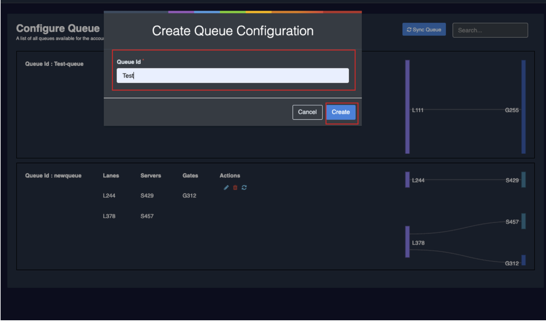
Click on “Create queue configuration” to initiate the setup process.
In the opening window, enter the name of the queue.
Click the “Create” button to proceed.
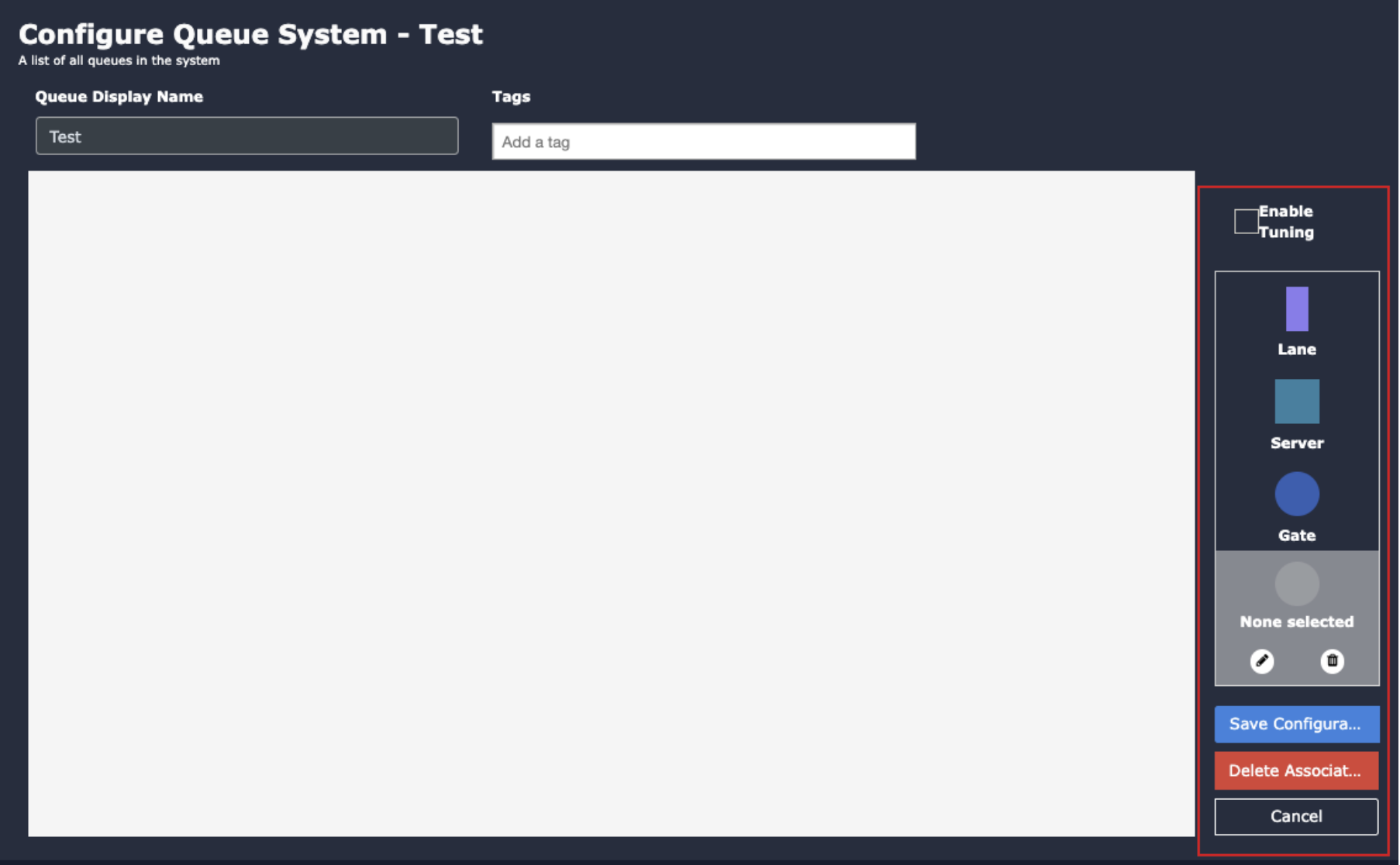
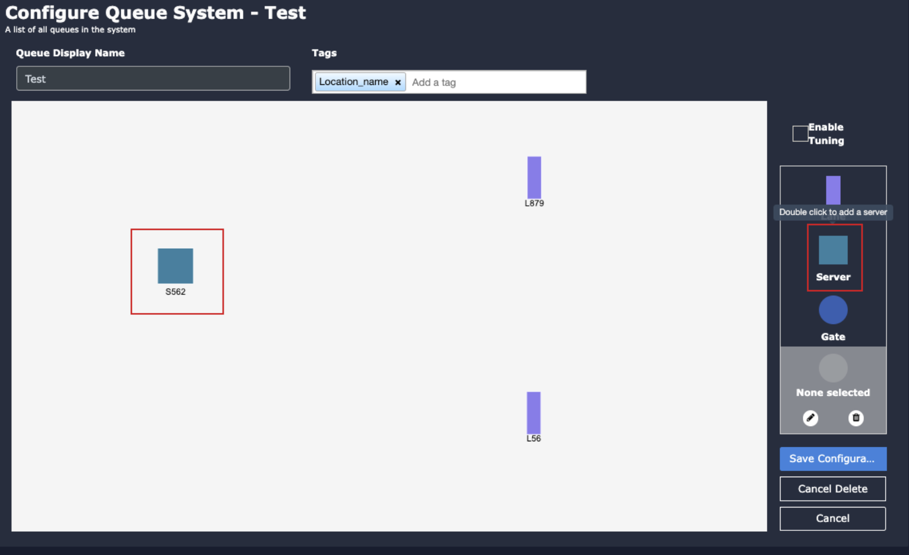
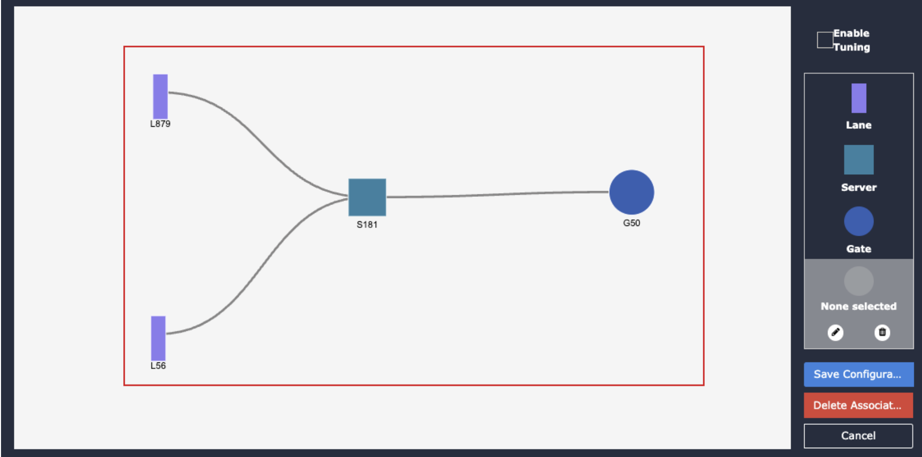
In the “Configure Queue System” window, you’ll find the Lane, Server, and Gate buttons on the right-hand side.
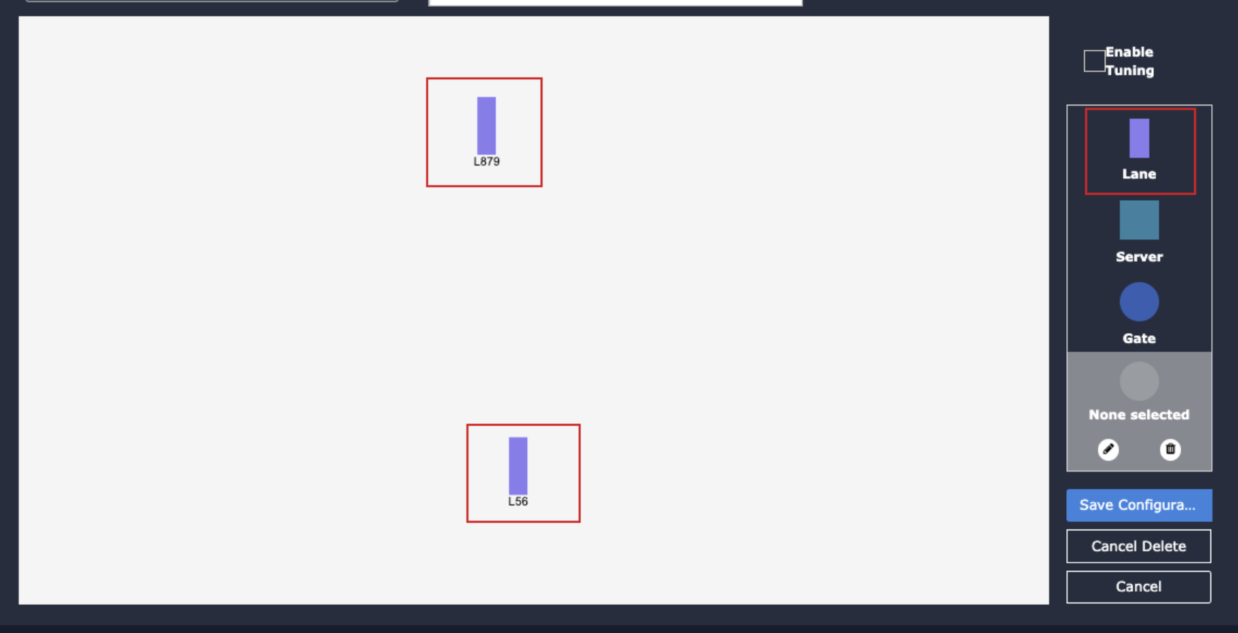
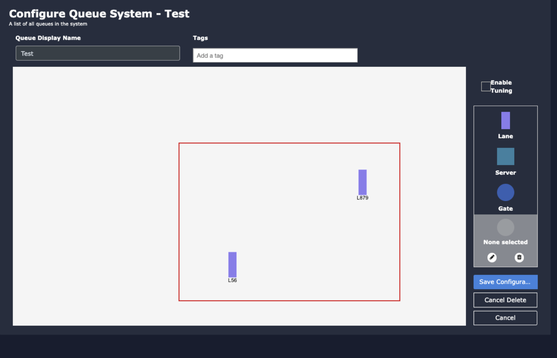
Add Lanes:
Double-click on the “Lane” button.
In the popup window, specify the number of lanes.
Click “Add” to add the lanes to the canvas.
4. Adjust the lane positions according to your requirements by dragging them.
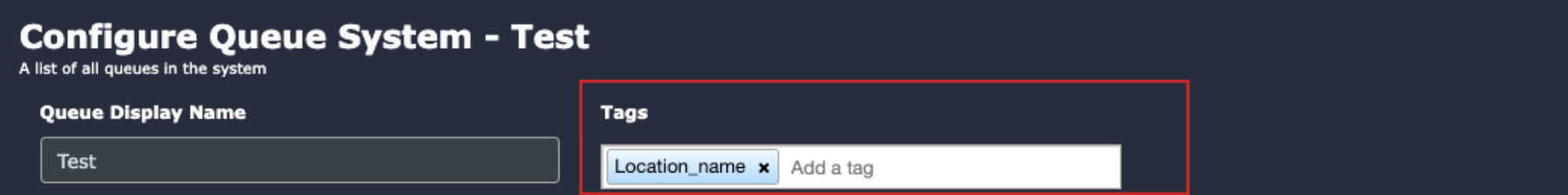
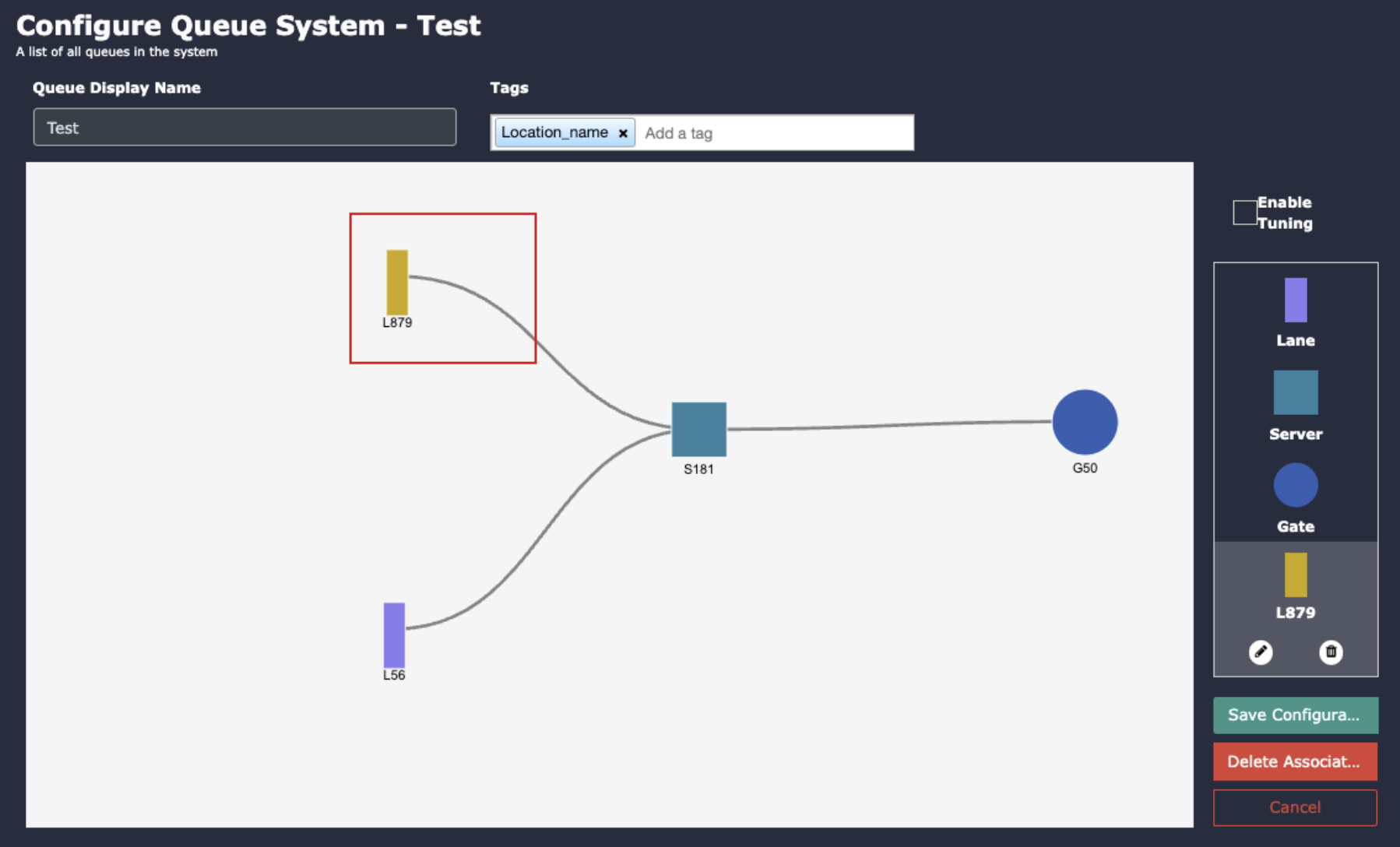
Add Tag:
You can right the reference location or any unique name as tag.
Add Servers:
Double-click on the “Server” button.
In the popup window, select the number of servers.
Click “Add” to add server gates to the canvas.
Adjust the server gate positions as needed.
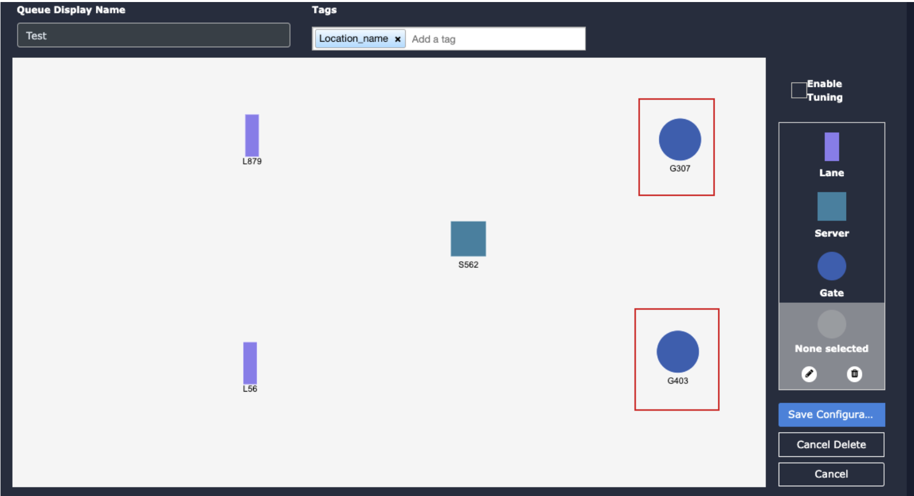
Add Exit Gates:
Double-click on the “Gate” button to add exit gates.
In the popup window, specify the number of exit gates.
Click “Add” to add exit gates to the canvas.
4. Adjust the exit gate positions according to your needs.
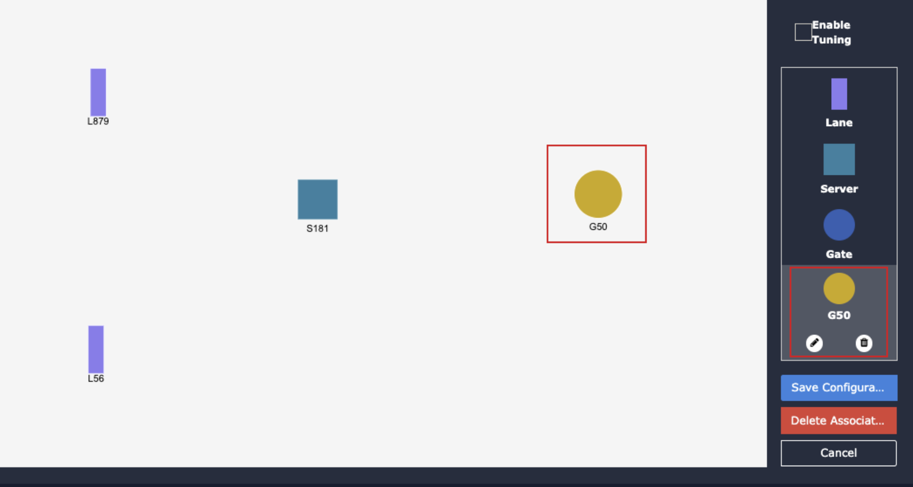
Draw Association Lines:
Click on the icon representing the association you want to create.
The selected icon’s color will change to yellow.
3. Click on the associated icon to create an association line between them.
4. Repeat the process to create associations between other icons.
Save Configuration:
Click the “Save Configuration” button to save the configured queue.
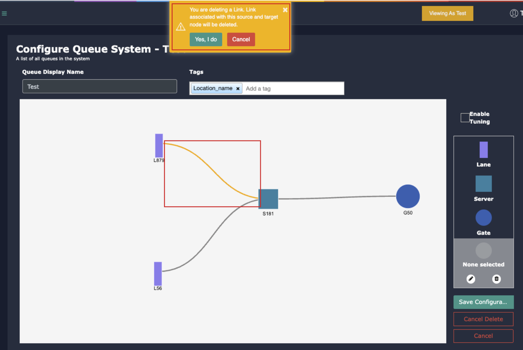
Delete Associations:
To delete an association, click on the “Delete association” button.
Select the association lane to be deleted.
A confirmation window will appear; click “Yes, I do” to confirm the deletion process.
4. Finally, click on the Save Configuration button to save the changes.
Management, Monitoring of KloudController
When monitoring is enabled for NVIDIA KloudController, it allows us to receive email notifications whenever the controller goes down. This is crucial for maintaining system reliability and ensuring timely intervention.
It is important to enable to this Alerts to Monitor the controller
Monitoring KloudController and Cameras
We can monitor the KloudController Active or In Active Status in the Kloud Manage Application by configuring the Alerts
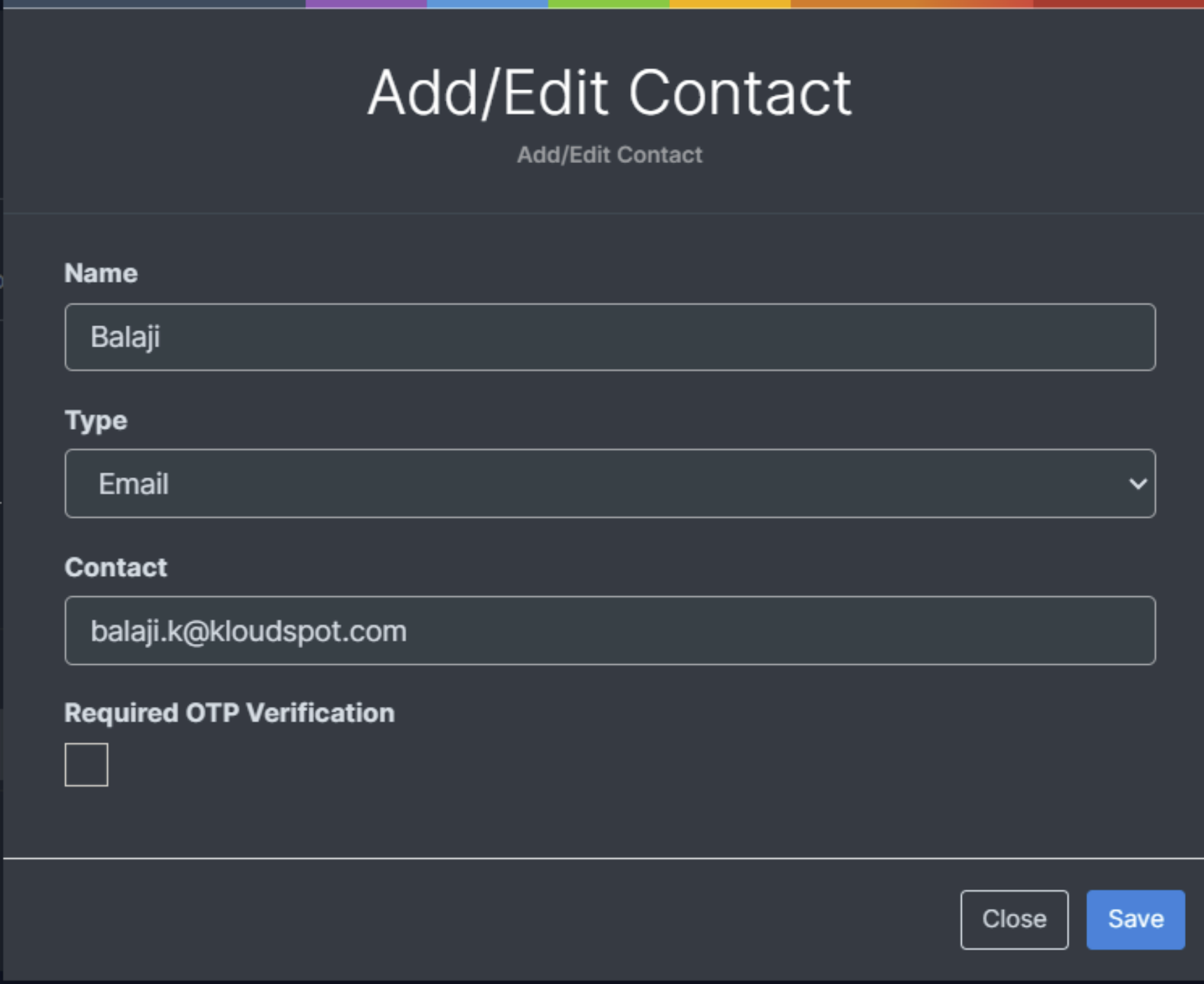
To configure Alerts first we need to create contact in Settings > Contacts> Click on +Contact
Provide the required information and select Type as Email
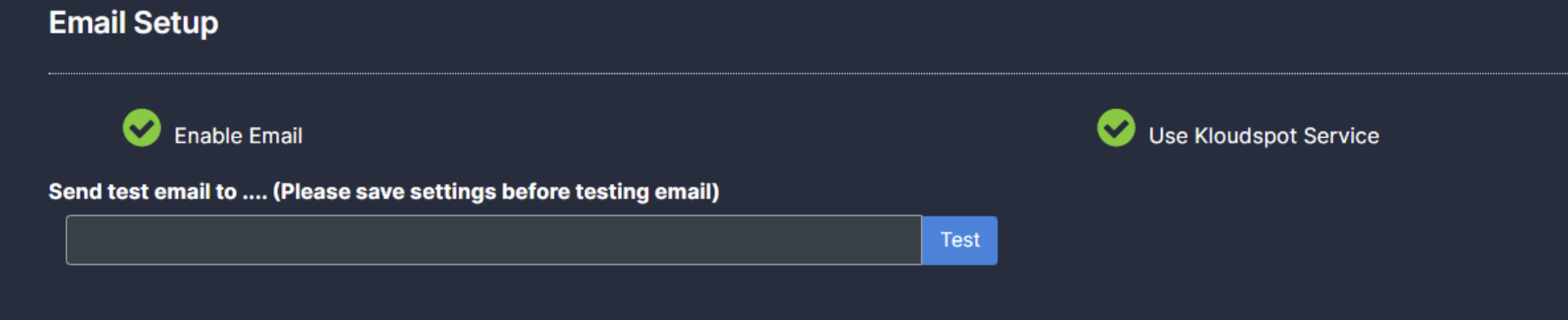
Before configuring the Alerts, please ensure that *** Email Setup is done in Settings> Third party settings***
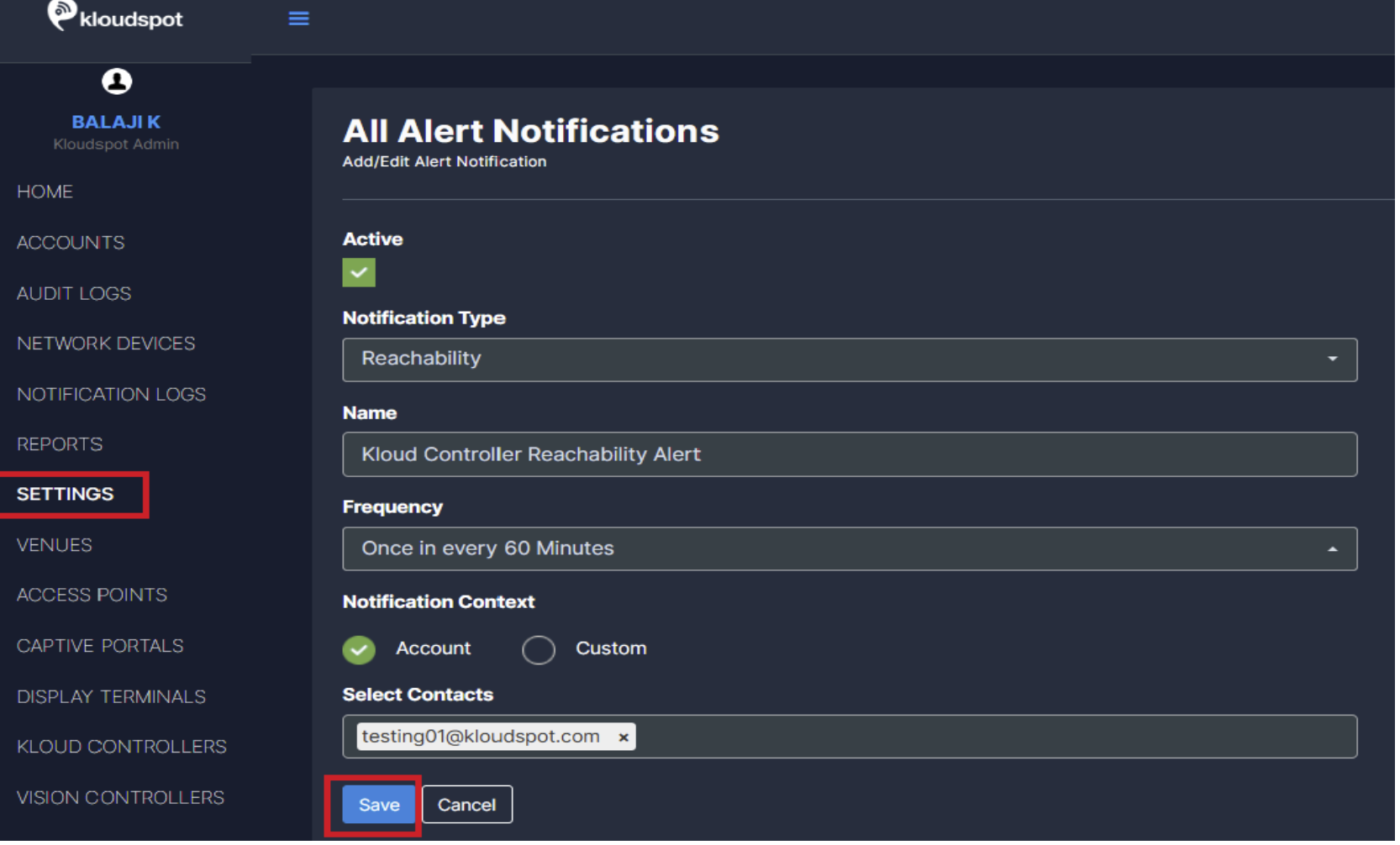
To Enable Alerts, Navigate to Settings > Alert Notifications
Click Add Alert Notification Button and configure alerts accordingly
Monitor and Manage KloudController Services
We Can Manage, Monitor and Troubleshoot KloudController from Kloud Manage
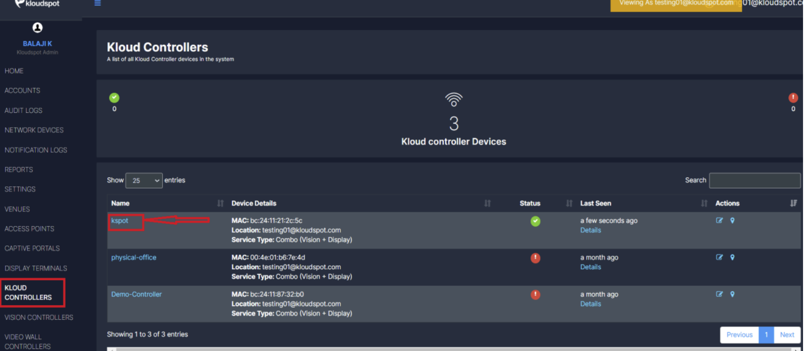
Navigate to Kloud Controller Tab
Select on the appropriate controller to monitor and manage it
Clicking on the controller’s name will fetch real-time information from the controller.
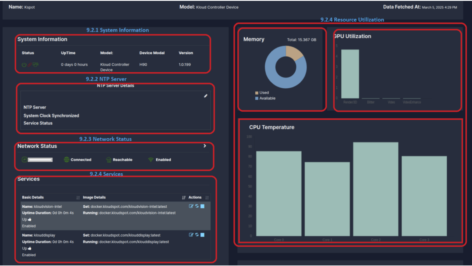
System Information
Status: Shows whether the controller is operational.
Device Power Red-> Power is down Green -> Power is UP
API Connection Red-> API Not Connected Green -> API Connected
(Note: If the API connection fails, there is no need to worry as data transfer is happening through WebSocket.)
WebSocket Connection Red-> WebSocket Not Connected
Green -> WebSocket Connected
Uptime: Displays the duration for which the device has been running.
Model & Version: Identifies the hardware and software version of the Kloud Controller
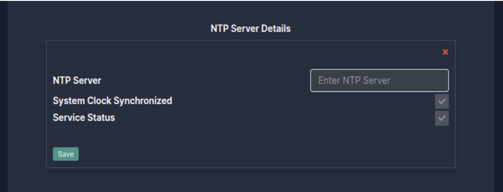
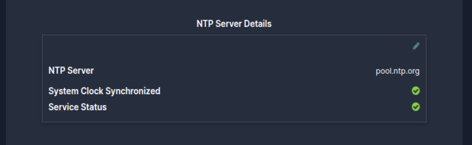
NTP Server
NTP Server: This section displays the NTP server details. If the controller is not Synced to an NTP server, the section will remain empty. An NTP server can be added or modified using the Edit button.
Once the NTP server is added we can verify the system clock synchronized status and service status as above
Network Status
IP Address: Shows the assigned IP (e.g., 192.168.1.2).
Connectivity Status: Indicates if the device is Connected, Reachable, and Enabled.
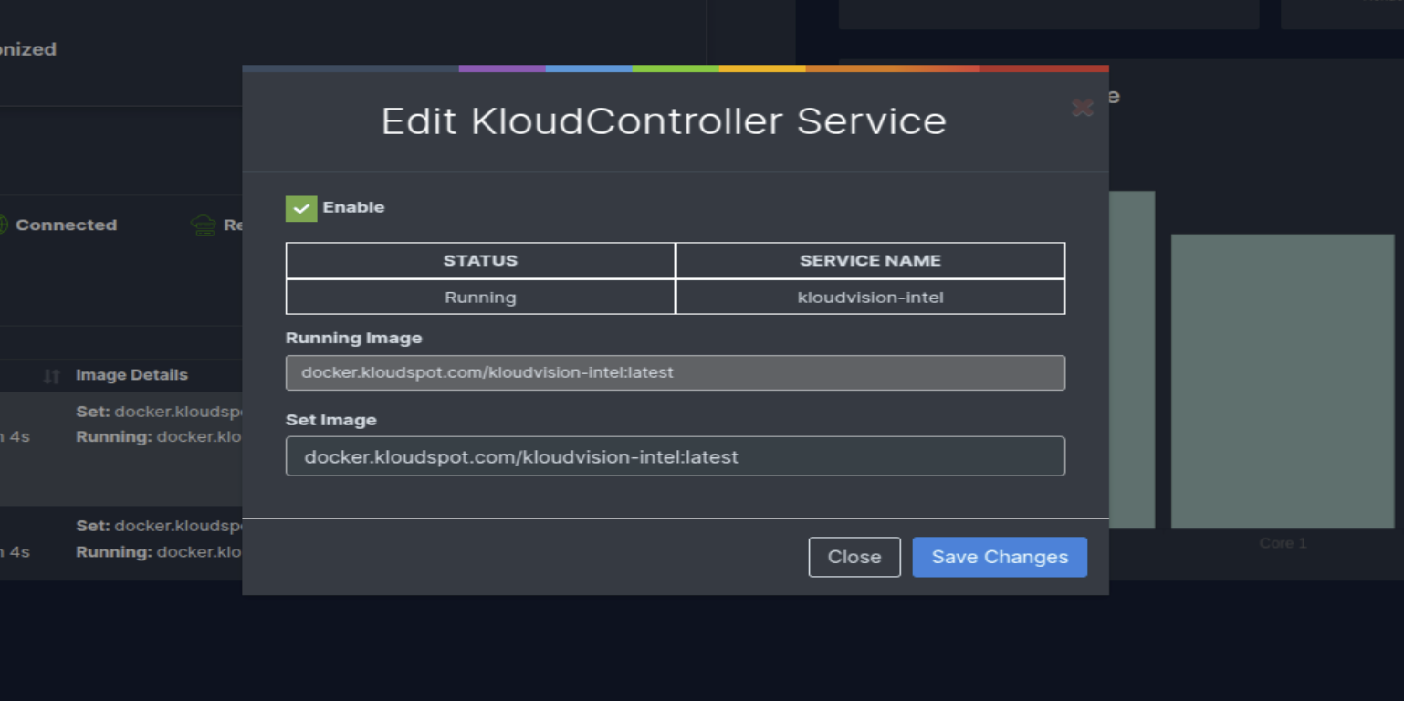
Services
This section displays the status of services, including whether they are Running, Not Running, Up, or Down, along with the associated Docker image name.
In the Action column, there are three buttons to:
Edit the image name.
Restart a service.
Start/Stop a service.
Clicking the Edit button opens a page where you can modify the image name and save the changes (We recommend checking latest image id with kloudspot Team) .
Resource Utilization
Memory Usage: Displays total available and used memory.
GPU Utilization: Shows GPU load distribution across different processing tasks.
CPU Temperature: Graphs per-core temperature readings.
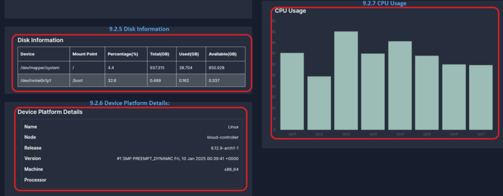
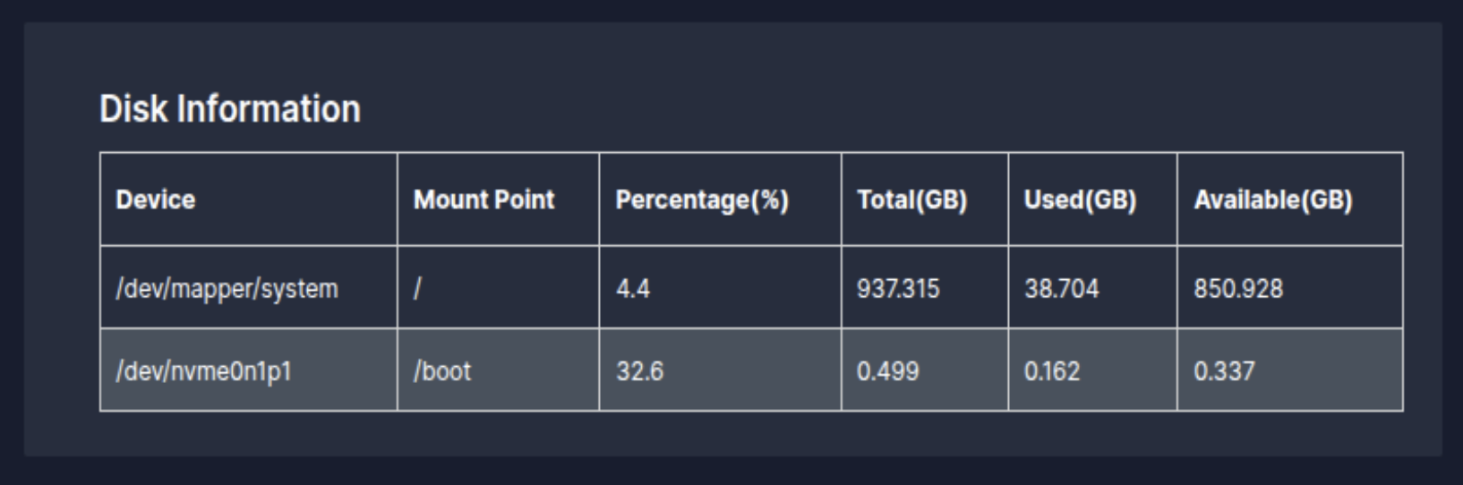
Disk Information
This section provides details about the storage devices, including mount points, total storage, used space, available space, and percentage usage.
Device Platform Details
Displays essential system information such as:
Operating System Name
Node (Hostname)
OS Release Version
Kernel Version
Machine Architecture (e.g., x86_64)
Processor Details
CPU Usage
A graphical representation of CPU utilization across different cores, helping in monitoring system performance.
Common Troubleshooting Scenarios
Troubleshooting scenarios can be performed by logging into TTY (Terminal).
(Please ensure a display is connected to the controller if it is not already attached.)
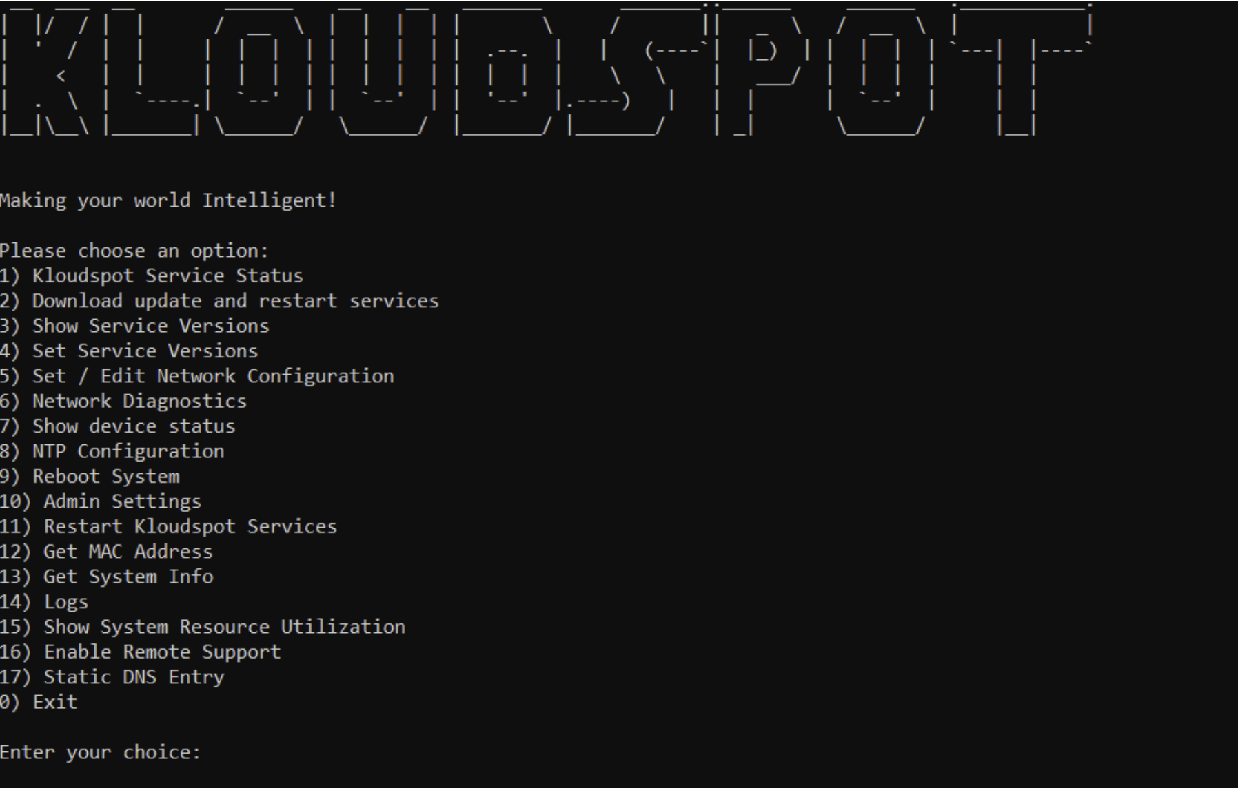
Steps to Access TTY:
Press ALT + Ctrl + F5 to switch to TTY5.
Enter the following credentials
Username: kloudspotPassword: kloudspot123
After successful we will be able to see below options
Installation Issues:
For troubleshooting Installation Issues please refer to 5.3 Troubleshooting Installation Issues
Network Connectivity:
What should we do if KloudController cannot connect to the internet?
Log in to the KloudController.
Check the IP address of the controller to verify whether the desired IP address has been assigned.
To verify the IP Address, refer to 5.4.1 Setting up Network Configurations
If the IP address is not assigned:
  Check the network connectivity to ensure the controller is properly connected.

  Verify DHCP settings if using automatic IP assignment.

  If a static IP needs to be configured, refer to the 5.4.1 Setting up Network Configurations for detailed steps
Once the IP is assigned, proceed with the following diagnostic steps:
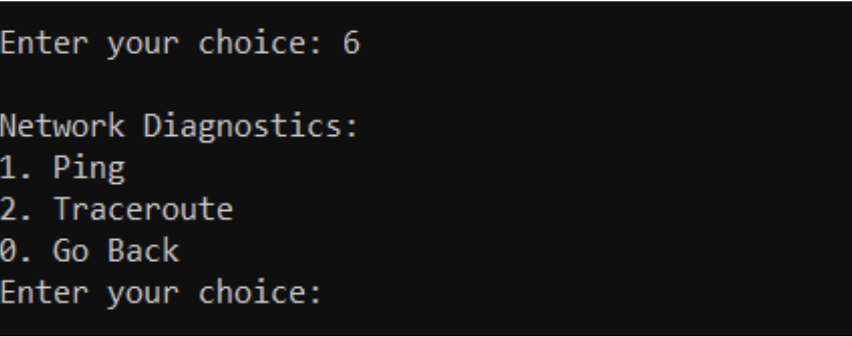
Choose option 6 to perform Network Diagnostics
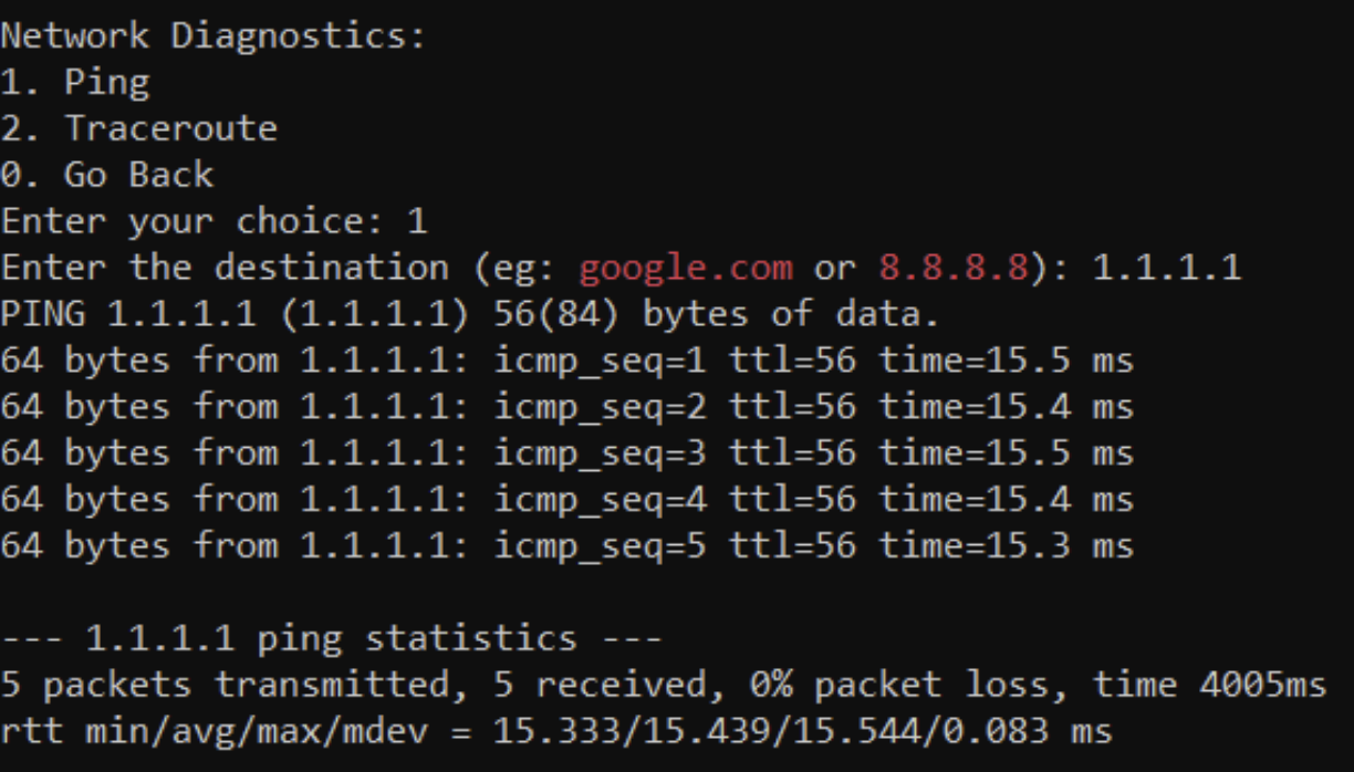
From the Network Diagnostics menu, choose Option 1 to run a ping test and check connectivity.
If the ping test fails, choose Option 2 to run a traceroute and diagnose network path issues.
If connectivity issues persist:
  Check the internet connection to the controller.

  Reboot the controller and repeat the steps above.
Are there specific diagnostics we should perform (e.g., checking DNS or NTP settings)?
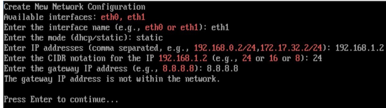
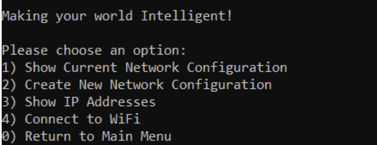
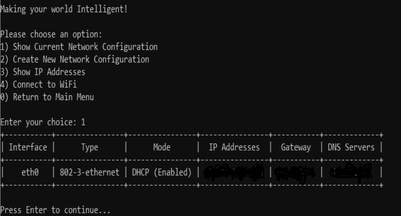
Users can also check and modify the current Network configuration by choosing option 5 in main menu
Verify Current Network Settings:
  Choose Option 1 to check details such as:
  - Network Interface
  - Mode
  - IP Address
  - Gateway
  - DNS Server
*For Security reasons few IP Address are hidden in above screenshot
Select Option 2 to set up a new network configuration if needed.
TO check NTP server settings refer to NTP COnfigurations
What should we do if KloudController cannot connect to the Kloudspot Platform?
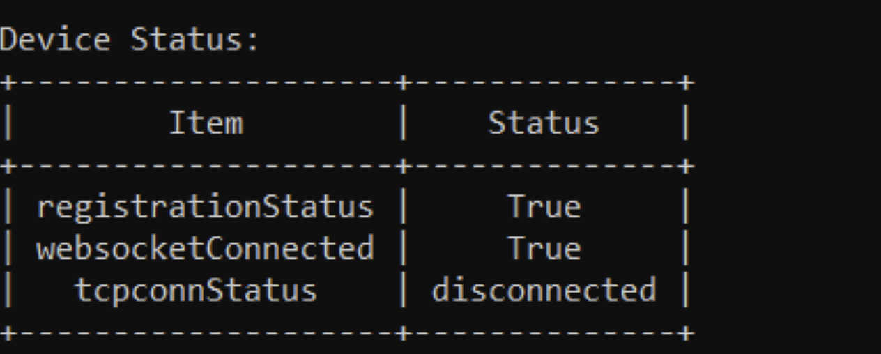
Select Option 7 to display the device status from the main menu
Registration Status – If the device is licensed, the status will be True; otherwise, it will be False.
WebSocket Connection – If the device is successfully connected to the application server, the status will be True; otherwise, it will be False.
If both Registration Status and Web Socket Connection is False, please contact Kloudspot Support Team to provide required Licence
TCP Connection Status – This is used for maintenance and software upgrades by the Kloudspot team. By default, the status is Disconnected. but it will be enabled when a Kloudspot engineer is working on the device.
What should we do if KloudController is not showing camera feed?
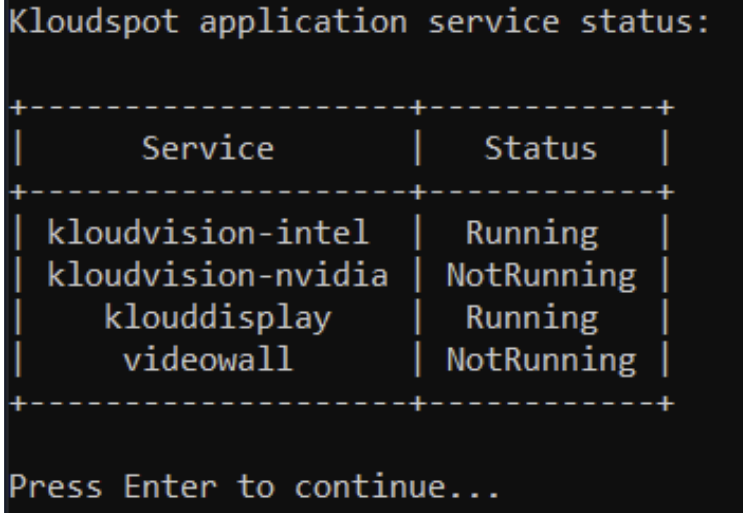
Choose Option 1 to check Kloudspot service status from the main menu
If services are updating, allow the controller to complete the update Successfully.
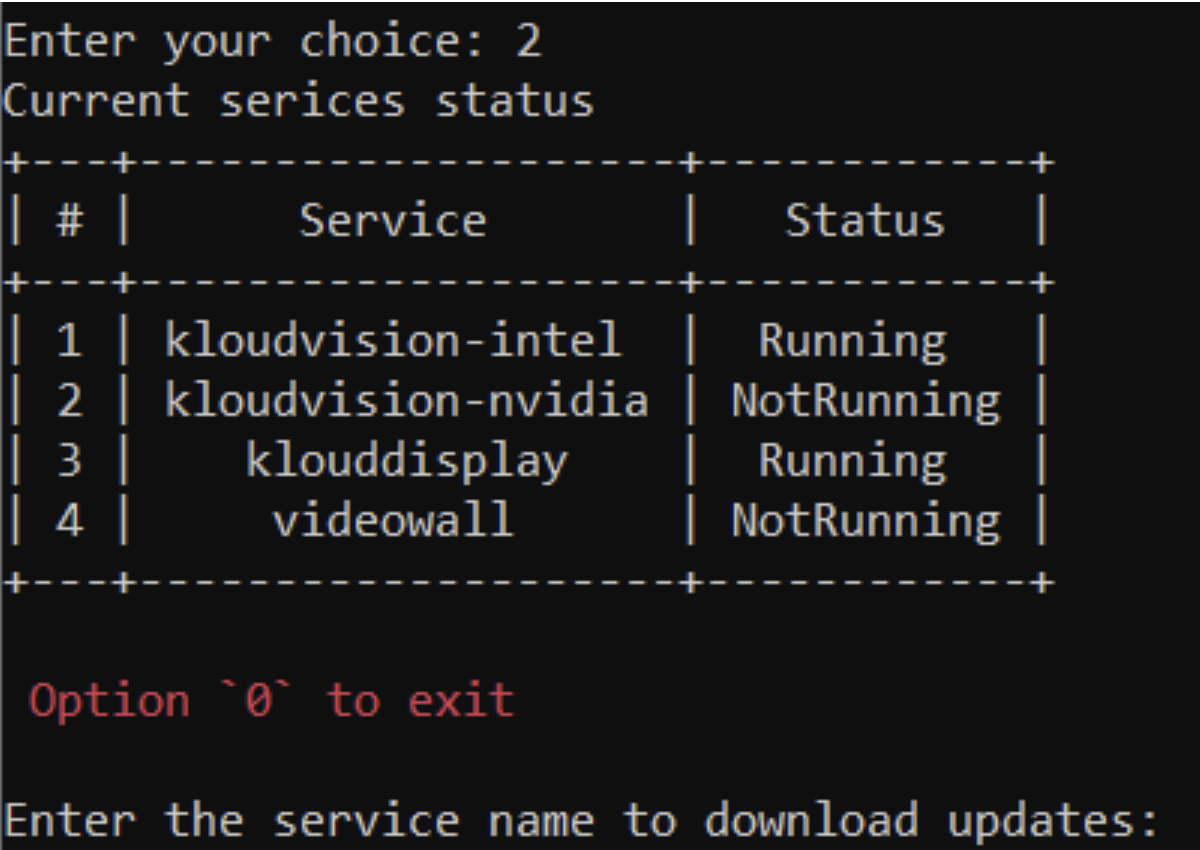
If the required services are not running, go back and choose Option 2 to download and restart the services.
Service Failures:
What is some typical service-related problems (e.g., KloudVision failing to connect to a camera)?
If KloudVision or another service fails to connect to a camera, check the following:
RTSP Port Blocked:
Ensure RTSP port 554 is enabled in the firewall or network settings.
If using a custom RTSP port, verify the correct port is configured.
Incorrect Camera Credentials:
Verify the username and password in the RTSP URL match the camera’s login credentials.
Check for any case-sensitive mismatches.
Test Raw Camera Feed:
Open VLC Media Player and try streaming the RTSP feed directly.
If the stream fails, the issue may be with the camera settings or network.
Camera Network & Configuration:
Ensure the camera is powered on and connected to the network.
Check if the camera IP address is correct and accessible.
Verify that the camera firmware is up to date.
Are there logs or tools users can check for troubleshooting these services?
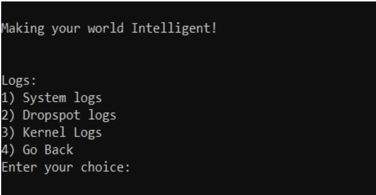
  * Users can check various logs using Option 14, which provides valuable insights into system behaviour and potential issues. Below is an overview of what each log contains:

  * If you need to exit from any logs press ctrl+c

  1. System Logs:

          a. Includes general system activity, errors, and events.
          b. Useful for diagnosing service failures, crashes, and hardware issues.
          c. Helps identify boot issues, network failures, or unexpected reboots.


  2. Drop spot Logs:
          a. Specific to Kloudspot services and Dropspot operations.
          b. Logs device registration, connectivity, and service interactions.
          c. Useful for diagnosing platform-related issues, such as data not syncing with Kloudspot.

  3. Kernel Logs:
          a. Contains low-level system events related to the Linux kernel.
          b. Logs hardware interactions, driver errors, and system stability issues.
          c. Useful for troubleshooting hardware failures, crashes, or performance bottlenecks.
Performance Issues:
What should users check if a service is running slower than expected (e.g., camera feeds in KloudVision lagging)?
If a service is running slower than expected, users should check the following:
Network Bandwidth & Latency:
a. Perform a ping test (Option 1 in Network Diagnostics) to check latency.
Device Resource Utilization:
 a.Check CPU and memory usage on the device to ensure it is not overloaded.
 b. Restart the device if resource usage is consistently high.
Camera-Specific Checks (For KloudVision):
a. Ensure the camera’s network connection is stable.
b. Verify that the camera stream settings (resolution, frame rate) are optimized for the network conditions.
c. Restart the camera and check for firmware updates.
Service Status & Logs:
 a. Use Option 1 to check the service status and ensure all necessary services are running.
 b. Check logs for any error messages that indicate performance issues.
 c. If the issue persists, try Download update and restart services using Option 2.
Any recommendations for optimizing performance (e.g., adjusting hardware resources)?
To improve performance and reduce lag in services like KloudVision, consider the following optimizations:
Network Optimization:
 a. Ensure a stable and high-speed internet connection with sufficient bandwidth for video streaming.
 b. Prioritize network traffic using QoS (Quality of Service) settings on your router.
 c. Reduce network congestion by limiting other high-bandwidth activities.
Hardware Resource Adjustments:
 a. Increase CPU & RAM allocation if the device is under heavy load.
 b. Use an SSD instead of an HDD for faster data processing.
 c. Ensure proper cooling to prevent performance throttling due to overheating.
Camera & Video Settings (For KloudVision):
 a. Adjust resolution and frame rate based on available bandwidth and processing power.
 b. Enable motion-based recording instead of continuous streaming to save resources.
 c. Keep camera firmware updated for performance improvements.
How Does NTP Configuration Affect Cameras and Connectivity to the Application Server?
Why is NTP (Network Time Protocol) important for system performance?
Proper time synchronization ensures accurate event logging, reduces
connectivity issues with the application server and prevents delays in camera feeds.
How can users configure NTP settings?
Select Option 8 to configure NTP settings.
Set the correct NTP server to synchronize time with a reliable source.
Restart services if necessary to apply changes.
What issues can occur if NTP is misconfigured?
Camera feeds may experience lag due to time drift.
Connectivity to the application server may be unstable if timestamps mismatch.
Event logs may have incorrect timestamps, making troubleshooting difficult.
Common Troubleshooting Scenarios
Troubleshooting scenarios can be performed by logging into TTY (Terminal).
(Please ensure a display is connected to the controller if it is not already attached.)
Steps to Access TTY:
Press ALT + Ctrl + F5 to switch to TTY5.
Enter the following credentials
Username: kloudspotPassword: kloudspot123
After successful we will be able to see below options
Installation Issues:
For troubleshooting Installation Issues please refer to 5.3 Troubleshooting Installation Issues
Network Connectivity:
What should we do if KloudController cannot connect to the internet?
Log in to the KloudController.
Check the IP address of the controller to verify whether the desired IP address has been assigned.
To verify the IP Address, refer to 5.4.1 Setting up Network Configurations
If the IP address is not assigned:
  Check the network connectivity to ensure the controller is properly connected.

  Verify DHCP settings if using automatic IP assignment.

  If a static IP needs to be configured, refer to the 5.4.1 Setting up Network Configurations for detailed steps
Once the IP is assigned, proceed with the following diagnostic steps:
Choose option 6 to perform Network Diagnostics
From the Network Diagnostics menu, choose Option 1 to run a ping test and check connectivity.
If the ping test fails, choose Option 2 to run a traceroute and diagnose network path issues.
If connectivity issues persist:
  Check the internet connection to the controller.

  Reboot the controller and repeat the steps above.
Are there specific diagnostics we should perform (e.g., checking DNS or NTP settings)?
Users can also check and modify the current Network configuration by choosing option 5 in main menu
Verify Current Network Settings:
  Choose Option 1 to check details such as:
  - Network Interface
  - Mode
  - IP Address
  - Gateway
  - DNS Server
*For Security reasons few IP Address are hidden in above screenshot
Select Option 2 to set up a new network configuration if needed.
TO check NTP server settings refer to NTP COnfigurations
What should we do if KloudController cannot connect to the Kloudspot Platform?
Select Option 7 to display the device status from the main menu
Registration Status – If the device is licensed, the status will be True; otherwise, it will be False.
WebSocket Connection – If the device is successfully connected to the application server, the status will be True; otherwise, it will be False.
If both Registration Status and Web Socket Connection is False, please contact Kloudspot Support Team to provide required Licence
TCP Connection Status – This is used for maintenance and software upgrades by the Kloudspot team. By default, the status is Disconnected. but it will be enabled when a Kloudspot engineer is working on the device.
What should we do if KloudController is not showing camera feed?
Choose Option 1 to check Kloudspot service status from the main menu
If services are updating, allow the controller to complete the update Successfully.
If the required services are not running, go back and choose Option 2 to download and restart the services.
Service Failures:
What is some typical service-related problems (e.g., KloudVision failing to connect to a camera)?
If KloudVision or another service fails to connect to a camera, check the following:
RTSP Port Blocked:
Ensure RTSP port 554 is enabled in the firewall or network settings.
If using a custom RTSP port, verify the correct port is configured.
Incorrect Camera Credentials:
Verify the username and password in the RTSP URL match the camera’s login credentials.
Check for any case-sensitive mismatches.
Test Raw Camera Feed:
Open VLC Media Player and try streaming the RTSP feed directly.
If the stream fails, the issue may be with the camera settings or network.
Camera Network & Configuration:
Ensure the camera is powered on and connected to the network.
Check if the camera IP address is correct and accessible.
Verify that the camera firmware is up to date.
Are there logs or tools users can check for troubleshooting these services?
  * Users can check various logs using Option 14, which provides valuable insights into system behaviour and potential issues. Below is an overview of what each log contains:

  * If you need to exit from any logs press ctrl+c

  1. System Logs:

          a. Includes general system activity, errors, and events.
          b. Useful for diagnosing service failures, crashes, and hardware issues.
          c. Helps identify boot issues, network failures, or unexpected reboots.


  2. Drop spot Logs:
          a. Specific to Kloudspot services and Dropspot operations.
          b. Logs device registration, connectivity, and service interactions.
          c. Useful for diagnosing platform-related issues, such as data not syncing with Kloudspot.

  3. Kernel Logs:
          a. Contains low-level system events related to the Linux kernel.
          b. Logs hardware interactions, driver errors, and system stability issues.
          c. Useful for troubleshooting hardware failures, crashes, or performance bottlenecks.
Performance Issues:
What should users check if a service is running slower than expected (e.g., camera feeds in KloudVision lagging)?
If a service is running slower than expected, users should check the following:
Network Bandwidth & Latency:
a. Perform a ping test (Option 1 in Network Diagnostics) to check latency.
Device Resource Utilization:
 a.Check CPU and memory usage on the device to ensure it is not overloaded.
 b. Restart the device if resource usage is consistently high.
Camera-Specific Checks (For KloudVision):
a. Ensure the camera’s network connection is stable.
b. Verify that the camera stream settings (resolution, frame rate) are optimized for the network conditions.
c. Restart the camera and check for firmware updates.
Service Status & Logs:
 a. Use Option 1 to check the service status and ensure all necessary services are running.
 b. Check logs for any error messages that indicate performance issues.
 c. If the issue persists, try Download update and restart services using Option 2.
Any recommendations for optimizing performance (e.g., adjusting hardware resources)?
To improve performance and reduce lag in services like KloudVision, consider the following optimizations:
Network Optimization:
 a. Ensure a stable and high-speed internet connection with sufficient bandwidth for video streaming.
 b. Prioritize network traffic using QoS (Quality of Service) settings on your router.
 c. Reduce network congestion by limiting other high-bandwidth activities.
Hardware Resource Adjustments:
 a. Increase CPU & RAM allocation if the device is under heavy load.
 b. Use an SSD instead of an HDD for faster data processing.
 c. Ensure proper cooling to prevent performance throttling due to overheating.
Camera & Video Settings (For KloudVision):
 a. Adjust resolution and frame rate based on available bandwidth and processing power.
 b. Enable motion-based recording instead of continuous streaming to save resources.
 c. Keep camera firmware updated for performance improvements.
How Does NTP Configuration Affect Cameras and Connectivity to the Application Server?
Why is NTP (Network Time Protocol) important for system performance?
Proper time synchronization ensures accurate event logging, reduces
connectivity issues with the application server and prevents delays in camera feeds.
How can users configure NTP settings?
Select Option 8 to configure NTP settings.
Set the correct NTP server to synchronize time with a reliable source.
Restart services if necessary to apply changes.
What issues can occur if NTP is misconfigured?
Camera feeds may experience lag due to time drift.
Connectivity to the application server may be unstable if timestamps mismatch.
Event logs may have incorrect timestamps, making troubleshooting difficult.
FAQ
General Questions:
What happens if the hardware specs are below the recommended requirements?
Running KloudController on lower specs may result in performance issues such as slower processing, reduced camera feed quality, or application crashes. It is recommended to upgrade the hardware to meet the minimum specifications for Optimal performance.
Can multiple users access KloudController simultaneously?
Yes, KloudController supports multi-user access
Can I access KloudController remotely when I’m not on the same network?
Yes, you can access KloudController remotely if remote access is configured through VPN, port forwarding, or cloud integration.
What should I do if I accidentally misconfigure the network settings?
You can reset the network settings by accessing the controller via a connected display and using the “Set/Edit Network Configuration” option.
Does KloudController store any of my personal data or logs? KloudController only stores system logs and service-related data for diagnostics. No personal data is collected
What happens if KloudController runs out of storage space? If storage is full, certain logs and non-critical data will be overwritten. It is recommended to monitor disk usage and expand storage if needed For monitoring Disk Usage Refer to 9.2.5 Disk Information
Service-Specific Questions:
KloudVision:
1.What types of cameras are supported?
KloudVision supports RTSP-compatible IP cameras, ONVIF cameras, and select USB cameras.
2.How many cameras can be configured to one KloudController?
The number of supported cameras depends on hardware specifications for more details refer to Hardware recomendation section
3.Can I access camera feeds remotely?
Yes, camera feeds can be accessed remotely if configured with proper security settings.
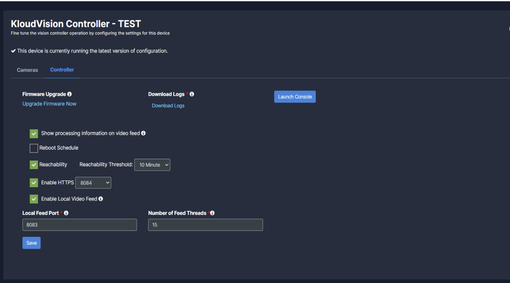
4.What should I do if my camera feed is not showing?
Ensure the camera is powered on, correctly connected to the network, and that the RTSP URL is correctly configured. Check weather services are running/Stopped
Make sure that you have Enabled below:
Enable HTTPS
Show Processing information on video feed
5. How does KloudVision’s face detection feature work?
KloudVision’s face detection feature identifies individuals who enter a premises, monitors their movements, and tracks their behaviour using AI and computer vision. It’s valuable for enhancing security and managing access in high- Security areas.
Support:
Where can I find Kloudspot’s documentation and user manuals?
All manuals, guides, and API documentation are available on the Kloudspot Documentation Portal.
How can I contact Kloudspot Support?
You can reach Kloudspot Support through Email: support@kloudspot.com